


© 2006 American Standard Inc. All Rights Reserved
4
18-HE58D1-3
Installer’s Guide
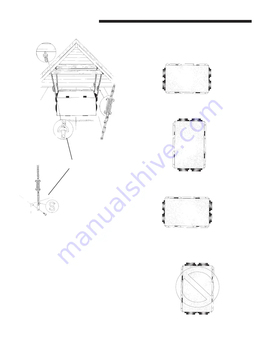
Figure 5
Be sure suspension hardware and fasteners are properly
selected to support the load.
UNIT MOUNTING POSITIONS
The unit may be installed in a variety of positions
EXCEPT as noted in Figure 6d.
APPROVED MOUNTING POSITIONS
HINGE
HINGE
Figure 6a - Hinges on Bottom
HINGE
HINGE
Figure 6b - Hinges on Right
HINGE
HINGE
Figure 6c - Hinges on Top
NOT AN APPROVED MOUNTING POSITION
HINGE
HINGE
Figure 6d - Hinges on Left
Do not install in this position, as door will fall off when opened
ALTERNATIVE MOUNTING
OPTION TO "D" RING


