


6
18-HE58D1-3
Installer’s Guide
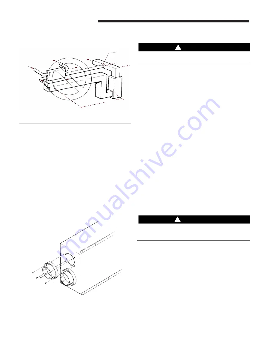
IV) EXHAUST AIR FROM RETURN DUCT / FRESH AIR
DUCTED TO SUPPLY AIR DUCT
Furnace
Minimum 3'
Minimum 3'
SA
RA
(to ERV)
OA
RA
(Furnace)
ERV
EA
FA
Install internal
elbow here
Figure 10
Note: Duct routing produces a negative pressure on
Exhaust Air and Adds additional pressure on Fresh Air
and can result in a greater than desired pressure differ-
ence and can make the house a negative pressure
volume. If a vented gas appliance is within the home's
envelope this duct application can cause flue gas
backdrafting.
INSTALL DUCT COLLARS
Attach one each of four duct collars to the fresh air inlet
and outlet, exhaust air inlet and outlet with the screws
provided in the plastic small parts bag. Use duct mastic
or equivalent approved caulk to form seal around
duct collar. (Optional) See figure 11.
Figure 11
DUCTWORK INSTALLATION - ERV TO EXTE-
RIOR WALL OUTLETS
CAUTION
!
Failure to follow this installation instruction may result in
property damage from sweating ductwork.
The fresh air duct and exhaust air duct connect the ERV to
the exterior wall outlet. Flexible or metal duct may be
used. The fresh air and exhaust air duct must be insulated.
Keep the fresh air supply and exhaust duct roughly equal
in length and as short and straight as possible. Typically,
six (6) inch insulated flexible duct is used for the
*ERVR100/200A9P00AA and eight inch for the
*ERVR300A9P00AA. If using flexible duct band or tape
the inner duct liner to the inner flange of appropriate
collar. Drive a sheet metal screw through the liner to
secure the duct spiral wire to the collar. Straighten
insulation, and slide the outer duct jacket onto the outer
flange of the duct collar. Secure with band or tape. The
outer flange of the duct collar can be used for both the
inner and outer jacket of eight (8) inch flexible duct. Care
must be taken to insure that the duct is securely fastened
and sealed to the duct collar.
If duct runs are exceedingly long (over 25 feet of duct for
the *ERVR100 or 300 and over 15 feet for the *ERVR200)
see the Air Conditioning Contractors Association of
America’s (ACCA) duct sizing manual “Manual D” to
design the appropriate sized ductwork.
FRESH AND EXHAUST AIR INLET AND OUT-
LET INSTALLATION
WARNING
!
Failure to follow the installation instructions for location
of the fresh air inlet and return air grilles could result in
Carbon Monoxide Poisoning or Death.
The fresh air inlet should be at least ten feet away from
any exhaust such as chimneys, furnace vents, water heater
exhausts, dryer vents, driveways or other sources of carbon
monoxide or contamination. Do not locate a fresh air inlet
where vehicles may be serviced or left idling. Never locate
the fresh air inlet inside a structure.
Do not install return air grilles (stale air return) in ga-
rages, or in the same room with any gas fired appliance; for
example a gas fired furnace, gas fired water heater, gas
dryer, etc.
Do not connect ERV ductwork to kitchen vent hoods
Do not connect a dryer directly to an ERV


