


8
18-HE58D1-3
Installer’s Guide
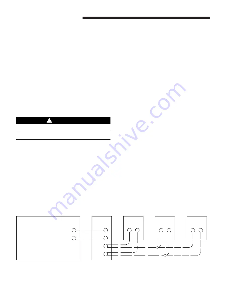
PT
ERV
PB
PB
PB
R
C
PB
PB
(2) PB controls can be directly connected to the PT control
Up to (6) PB controls, wired in parallel, may be used.
insulated flexible duct from the ERV port labeled “Fresh
Air To Inside” to the point of termination.
During winter, since fresh air is unconditioned, the fresh
air supply grilles should be located in a traffic area like a
hallway or stairway rather than in a sitting area. Locate
fresh air supply register within 12 inches of the ceiling on
an inside wall pointing the register louvers toward the
ceiling.. If fresh air is desired in specific rooms with high
occupancy the fresh supply air can be split among the
additional rooms.
RETURN AIR FROM HOUSE
Locate return air grilles in rooms where moisture and
odors are generated. Preferred locations for returns are
bath rooms, kitchens and hallways. Return grilles should
be installed within 12 inches from the ceiling on an inside
wall. Do not use returns to vent cooking areas. Do not
connect returns to a vent hood.
ELECTRICAL CONTROLS
WARNING
!
Hazardous Voltage – Disconnect Power Before Servicing
Note: Proper Wiring Size Selection and Wiring Installa-
tion Is The Responsibility of the Electrical Contractor.
Controls
A percent timer (PT) control is included in the box with
the ERV. This is the primary control for operation of the
ERV. After startup, the PT control will operate the ERV
automatically. The PT control should be set by the install-
ing dealer.
To assist the dealer in determining the PT control setting
a ventilation calculator is available from your local
distributor. MicroSoft Excel is required to run this
program. The calculator input can accept a minimum
ventilation airflow requirement per local code or calculate
the minimum airflow required per ASHRAE 62.2-2004.
In addition to the PT control some installations may
include Push Button (PB) or point of use control(s). The
PB controls are typically located in bathrooms or areas
where exhaust ventilation is required for short periods of
time. PB controls are wired in parallel to the PT controls
and energize the ERV whenever there is a manual call for
ventilation.
PERCENT TIMER CONTROL (PT)
The Percent Timer Control automatically energizes and
de-energizes the energy recovery ventilator every hour,
ensuring ventilation for the home around-the-clock. The
PT control has two status lights . One is the power light
located in the upper left hand corner of the control. The
other is the Runtime % light. The power light is on
whenever the PT control is calling for the ERV to run.
The Runtime % light is located on the right side of the
control. The Runtime % light indicates the amount of
time per hour the ERV will operate. Set the control per
your local code or ASHRAE Std 62.2 and your ventilator
will run once every hour.
FOR CONSTANT OPERATION: Press the fan icon
until the 100% light is on. The “Runtime %” light turns
on. The ERV unit will run continuously.
FOR MINIMUM VENTILATION REQUIREMENT
OPERATION: Set the control at the percentage that
meets local code or ASHRAE 62.2. Press the fan icon until
the light for the percent desired is on.
TO TURN THE ERV OFF: Press the fan icon until all
lights are off. The control is off. The ERV motor is de-
energized. (Power is still persent inside the unit. Always
unplug cord from outlet before servicing!)
Figure 14


