Installation Instructions
Page 9
Pub. No. 41-5016-12
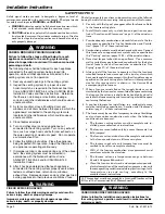
Downflow Furnaces: Brackets are factory supplied to mount filters
in the return air duct work.
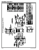
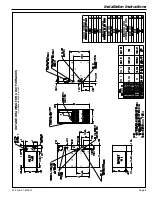
7. Connect duct work to furnace. See Outline Drawing for supply
and return duct size and location. Flexible duct connectors are
recommended to connect both supply and return air ducts to the
furnace. If only the front of the furnace is accessible, it is recom-
mended that both supply and return air plenums are removable.
8. When replacing a furnace, old duct work should be cleaned out.
Thin cloths should be placed over the registers and the furnace fan
should be run for 10 minutes. Don’t forget to remove the cloths
before you start the furnace.
RETURN AIR FILTERS
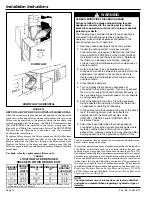
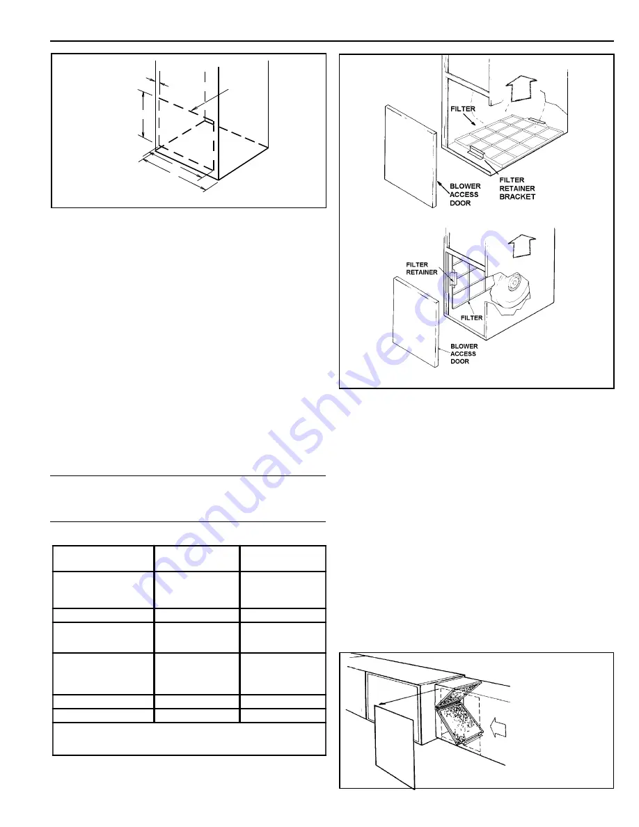
Filters are
not
factory supplied for these furnaces. These furnaces
require high velocity type air filters which may be located within
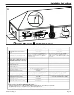
the furnace blower compartment for UPFLOW furnaces in either
a BOTTOM or SIDE (left side or right side) return air inlet. See
Figure 11. Some filters may need to be trimmed for side or bottom
filter use. Downflow furnaces must be located outside the furnace
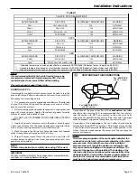
cabinet. Typical installations are shown in Figure 12. Table 5
provides information for installation of the filter retaining brackets
shipped with downflow furnaces.
NOTE:
On upflow 5 ton airflow models, if the airflow requirement
exceeds 1800 CFM, these models will require filters on both
sides; OR 1 side and the bottom; OR just the bottom.
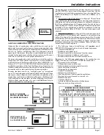
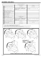
* SEE OUTLINE DRAWING
LOCATING
NOTCHES
PROVIDED
FOR SIDE
RETURN
CUTOUT
*
*
*
*
CUT OUT
FOR
SIDE
FILTER
FRONT
of Furnace
FIGURE 10
FILTER RETAINER BRACKETS FOR
SIDE AIR RETURN ON UPFLOW FURNACES
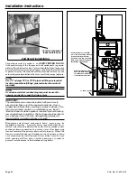
If side air return is desired, it is necessary to move the 2 filter
retainer brackets from the bottom of the furnace and reinstall
them on the side. The following instructions should be used:
a. Remove the front doors.
b. Remove the filter.
c. Carefully place the unit on its back.
d. Using a 5/16" nut driver, remove the 4 screws holding the
filter retainer brackets.
e. Reinstall the filter retainer brackets on the desired side.
(See Figure 11 “Typical Side Return Filter”).
TYPICAL UPFLOW FURNACE RETURN AIR FILTER
INSTALLATIONS FIGURE 11
RETURN AIR FILTERS FOR UPFLOW FURNACE IN
HORIZONTAL CONFIGURATION
When the Upflow Furnace is installed in the horizontal configura-
tion, the return air filters must be installed exterior to the cabinet.
Remote filter grilles may be used for homeowner convenience or the
filters may be installed in the duct work upstream of the furnace.
See Figure 11A.
Typical Side Return Filter
Typical Bottom Return Filter
FIGURE 11
Airflow
Airflow
Airflow
FIGURE 11A
TABLE 4
MODELS
NUMBERS
CABINET
WIDTH
FILTER
QTY & SIZE
CUX1B040A9241A
CUX1B060A9361A
CUX1B080A9421A
17-1/2"
1 - 17" X 25" X 1"
CUX1C100A9481A
21"
1 - 20" X 25" X 1"
CUX1D100A9601A#
CUX1D120A9601A#
24-1/2"
1 - 24" X 25" X 1"
CDX1B040A9241A
CDX1B060A9361A
CDX1B080A9421A
17-1/2"
2 - 14" X 20" X 1"
CDX1C100A9481A
21"
2 - 16" X 20" X 1"
CDX1D120A9601A
24-1/2"
2 - 16" X 20" X 1"
# -NOTE - On the upflow 5 ton airflow models, if the airflow
requirement exceeds 1800 CFM, these models will require filters on
both sides; OR 1 side and the bottom; OR just the bottom.


