background image

2

755741-100 EN

AS DESIRED

F

CUTOUT

AS

DESIRED

G

CUTOUT

C

MOUNTING 

SURFACE

WATERPROOF 

SEALANT

BATH

TILE

TILE

BEAD

STRIP

LEVELING STRINGER 

1" x 4" (25mm x 102mm)

not for support

BATH

ADHESIVE

SEALANT

WALLBOARD

  NOTE:  Tile bead kit not included and must be purchased separately.

TYPICAL TILE BEAD INSTALLATION

C

E

D

W

LEVELING

STRINGERS

ROUGH-IN REFERENCES FOR 

RECESS TYPE INSTALLATIONS

ROUGH-IN REFERENCES FOR 

PIER TYPE INSTALLATIONS

Please note that care must be taken to protect the surface of the tub 
during all aspects of the installation.
Do not drill or cut the bath deck with the tub directly beneath it as 
damage to the tub may result.

1.   Install the tub per the installation instructions provided with the unit.
2.   Prepare the bath deck support structure per the local codes. 
      Note - the bath deck must be self supporting.
3.   Cut bath deck to your specifications.
4.   Place the bath deck in position and trace the opening on the tub 

with a soft pencil. Do not drill or cut the bath deck with the tub 
directly beneath it as damage to the tub may result.

5.   Remove the bath deck and apply a generous bead of waterproof 

sealant on the outer edge of the traced line.

6.   Replace the bath deck and secure it into place.
7.   Apply additional sealant along the tub and bath deck interface as 

necessary to ensure a watertight seal.

8.   Remove excess sealant per the manufacturer's instructions.

Finished bath deck surface 

material must be self-supporting 

and secured per local codes

Tub support 

structure per 

installation 

instructions 

provided with 

the tub 

Bath deck 

support 

material

Bathtub

Waterproof Sealant

UNDER DECK MOUNTING INSTRUCTIONS

NOTE: 

FRONT EDGE OF BATH 

MUST BE SUPPORTED BY STUD WALL.

Summary of Contents for DEEP SOAK 1640.305 Series

Page 1: ...INSTRUCTIONS Each bath arrives ready for installation however a drain overflow kit is required for each bath and it is not included The variety of installations for this bath may require framing proce...

Page 2: ...support structure per the local codes Note the bath deck must be self supporting 3 Cut bath deck to your specifications 4 Place the bath deck in position and trace the opening on the tub with a soft...

Page 3: ...m 2 51mm C L OF OVERFLOW LEVELING STRINGER NOT FOR SUPPORT 72 1829mm 36 914mm 11 1 2 292mm 14 3 4 375mm C L 9 229mm 19 483mm 2 51mm OUTLINE OF CUTOUT 70 5 x 34 5 1780 x 876mm 21 533mm 4 102mm INTEGRAL...

Page 4: ...wing 1 Defect or damages arising from shipping installation alterations accidents abuse misuse lack of proper maintenance and cleaning as directed in the Installation Instruction Manual and use of oth...

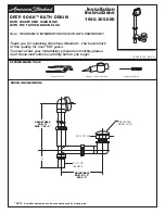
Page 5: ...100 years To ensure that your installation proceeds smoothly please read these instructions carefully before you begin Plumbers Putty or Caulking Phillips Screwdriver Channel Locks DEEP SOAK BATH DRAI...

Page 6: ...3 Apply sealant to threads of TAILPIECE 6 and thread into DRAIN TEE 3 Install OVERFLOW GASKET 4 to OVERFLOW TUBE ASSEMBLY 2 Adjust OVERFLOW GASKET 4 to couture of tub FIG 1 Loosen SLIP JOINT NUT SEAL...

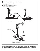
Page 7: ...r below floor Fig 1 TYPICAL ABOVE FLOOR INSTALLATION 4 ABOVE FLOOR OUTLET INSTALLATION STANDARD DRAIN ABOVE FLOOR ROUGH BELOW FLOOR ROUGH TUB NOTE TUB IS SHOWN CUT AWAY FOR CLARITY OF INSTALLATION DO...

Page 8: ...to 6 00 p m EST IN CANADA 1 800 387 0369 TORONTO 1 905 306 1093 Weekdays 8 00 a m to 7 00 p m EST Product names listed herein are trademarks of American Standard Inc American Standard Inc 2007 754129...

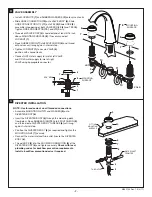
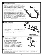
Page 9: ...with LOCKNUT 6 Supplied with Fittings MOUNTING SURFACE 165 mm to 305 mm ADJ 6 1 2 TO 12 38 mm 1 1 2 MAX 32 mm 1 1 4 MAX 31 mm 1 3 16 DIA 76 mm 3 1 2 NPT 1 2 NPT 40 mm 1 5 8 DIA H C 29 mm 1 1 8 DIA 20...

Page 10: ...ly Check with local plumbing codes for backflow prevention requirements Install a backflow prevention device if required DIVERTER INSTALLATION FITTING MOUNTING SURFACE WATER INLET FROM TEE TUB OUTLET...

Page 11: ...from HANDLE ADAPTER 3 Loosen the adapter screw 4 Use a flat blade screw driver to remove SPRING CLIP 5 Lift STOP WASHER 6 turn 90 and replace Replace SPRING CLIP 5 Reinstall HANDLE ASSEMBLY 2 and tigh...

Page 12: ...ER 2 and HOSES for leaks Turn VALVES off If spout drips operate handles several times from OFF to ON position Do not force handles turn only 90 TEST INSTALLED FAUCET CAUTION The flow rate of this Tub...

Page 13: ...0070A TUBE TEE ASSEMBLY M970262 0070A SHANK KIT 030274 0070A SHANK MOUNTING KIT 911903 0070A RUBBER RING 028664 YYY0A HAND SHOWER HOLDER 1660207 XXX HAND SHOWER 918319 0070A SCREW M918464 0070A SPINDL...

Reviews: