26
18-CE12D1-1D-EN
General Venting
FURNACE EXHAUST MUST BE VENTED TO THE OUTDOORS. THESE
FURNACES ARE INDUCED DRAFT VENTED AND MUST
NOT
BE
CONNECTED TO ANY VENT SERVING ANOTHER APPLIANCE. PLEASE
NOTE THAT THESE FURNACES USE
POSITIVE-PRESSURE
VENT
SYSTEMS.
Proper venting is essential to obtain maximum efficiency from a
condensing Furnace. Proper installation of the vent system is
necessary to assure drainage of the condensate and prevent
deterioration of the vent system.
ETL has certified the design of condensing Furnaces for a minimum of
0" clearance from combustible materials to single wall plastic vent
pipe.
The recommended system is assembled from 2" or 3" plastic pipe and
fittings found in the Approved Vent Pipe Materials Table. Where the
system is routed to the outdoors through an existing masonry
chimney containing flue products from another gas appliance, or
where required by local codes, then 3" venting of Type 29- 4C
stainless steel must be used in place of PVC material.
These Furnaces have been classified as CATEGORY IV Furnaces in
accordance with ANSI Z21.47 “latest edition” standards. Category IV
Furnaces operate with positive vent pressure and with a vent gas
temperature less than 140°F above the dewpoint. These conditions
require special venting systems, which must be gas tight and water
tight.
Note:
When an existing Furnace is removed from a venting system
serving other gas appliances, the venting system is likely to be
too large to properly vent the remaining attached appliances.
Important:
These Furnaces may be installed as Direct Vent (sealed
combustion) or as Nondirect Vent (single pipe). The
Furnaces are shipped DIRECT VENT with sealed
combustion.
Important:
Products installed in Canada must use vent systems that
are certified to the Standard for Type BH Gas Venting
Systems (ULC S636) for Class II-A venting systems (up
to 65°C). Components of the vent system must not be
interchanged with other vent systems or unlisted pipe or
fittings. Plastic components, specified primers, and glues
must be from a single system manufacturer and not
intermixed with other system manufacturer's vent
system parts. In addition, the first three feet of the vent
pipe must be visible for inspection.
When the vent pipe is exposed to temperatures below
freezing, e.g., when it passes through unheated spaces, etc.,
the pipe must be insulated with 1/2 inch (12.7 mm) thick
Armaflex-type insulation or equal.
If the space is heated sufficiently to prevent freezing, then the
insulation will not be required. If domestic water pipes are not
protected from freezing then the space meets the condition of
a heated space.
3” Venting requirements
Important:
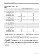
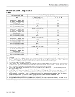
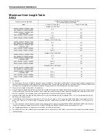
To determine if your application requires 3” venting, see
the Maximum Vent Length Table.
Important:
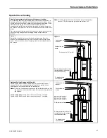
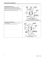
Horizontal venting application must use the 2” x 3” offset
reducing coupling. Vertical venting applications do not
require the reducing coupling to be offset.
Note:
If your furnace comes with a factory supplied 2" X 3" offset
reducing coupling it is used for 3" vent pipe installation. Make
sure the marking "TOP" is located on the top side of the pipe in
horizontal venting applications. The straight side of the
coupling must be on bottom for proper drainage of condensate
Note:
For Canadian applications, BAYREDUCE 2” x 3” offset reducing
coupling meets ULC-S636 requirements. Make sure the
marking "TOP" is located on the top side of the pipe. The
straight side of the coupling must be on bottom for proper
drainage of condensate in horizontal venting.
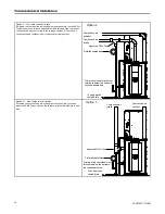
FIELD SUPPLIED
2” COUPLING
LABEL
SAYS
“TOP”
2" TO 3" COUPLING
CPL00938
BAYREDUCE may be
used in Canadian
applications to meet
ULC-S636
CPL00938 IS FACTORY
SUPPLIED ONLY WITH THE
120,000 BTUH UPFLOW
FURNACE MODELS
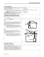
FIELD SUPPLIED
2” COUPLING
2" TO 3" COUPLING
CPL00938 IS FACTORY
SUPPLIED ONLY WITH THE
120,000 BTUH UPFLOW
FURNACE MODELS
CPL00938
BAYREDUCE may be
used in Canadian
applications to meet
ULC-S636


