18-CE03D1-1F-EN
59
O
BK
BK
Y2
Y1
Y1
B/C
B/C
W2
W1
W1
G
G
R
R
O
Y1
B/C
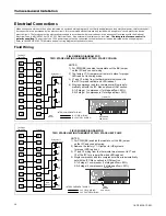
Single Stage
Thermostat
Furnace
Outdoor Unit
(No Transformer)
SEE
NOTE 2
SEE
NOTE 4
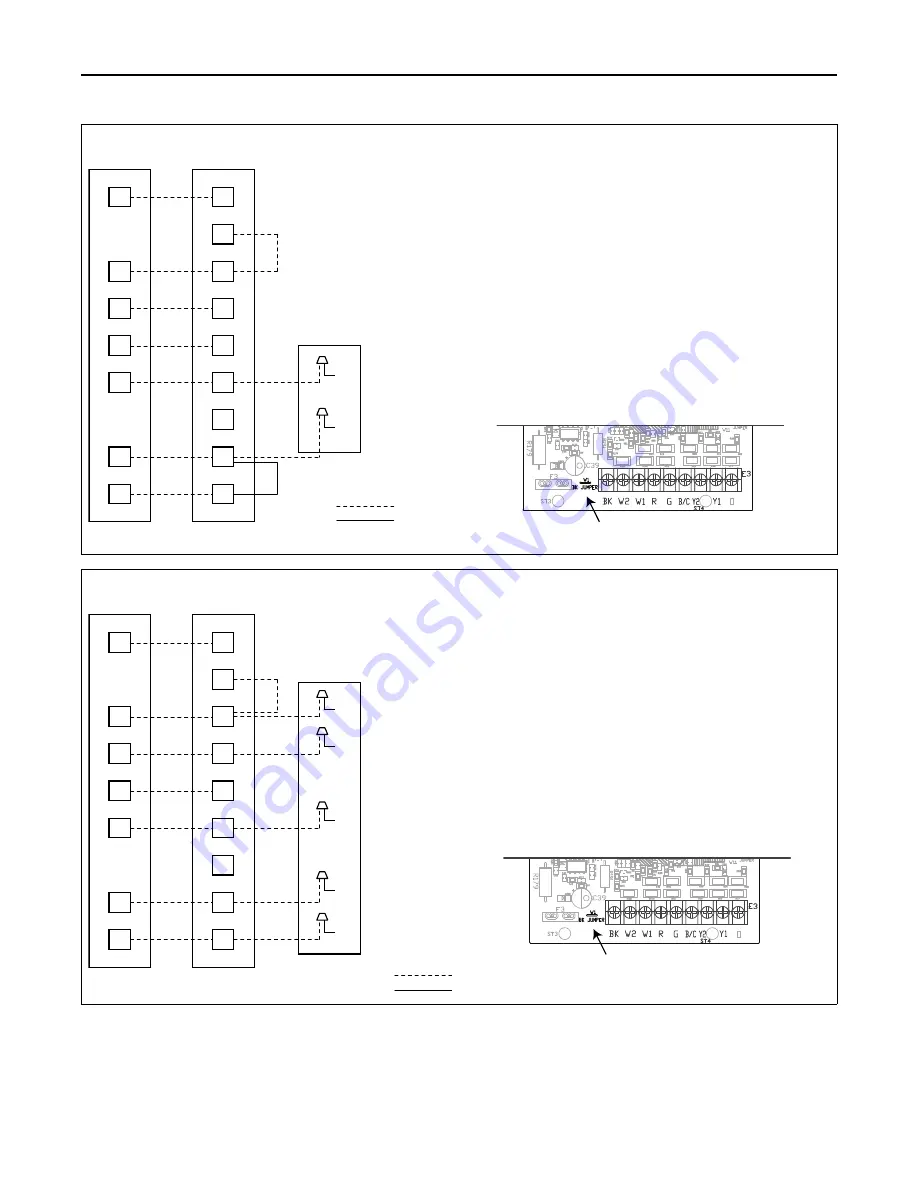
FIELD WIRING DIAGRAM FOR
SINGLE STAGE HEATING THERMOSTAT, SINGLE STAGE COOLING
NOTES:
1) For PWM (BK) enabled thermostats, cut the BK jumper
on the IFC and connect wiring.
2) The factory Y1-O jumper must remain in place for proper
LED read out in cooling mode.
3) Y1 wiring from the thermostat must connect to Y1 of
the IFC for proper airflow and LED readout.
4) Place field supplied jumper between W1 and W2 on the
IFC. Interstage delay is factory set for 10 minutes but is field
adjustable with the Menu option in the ISD section.
5) Single stage airflow is set with the IFC Menu options
in ODU section. Select 1-1.
INTER-COMPONENT WIRING
24 V FIELD WIRING
24 V FACTORY WIRING
Furnace IFC
BK JUMPER
SEE NOTE 1
O
BK
BK
Y2
Y1
Y1
B/C
B/C
W2
W1
W1
G
G
R
R
O
Y1
B/C
Single Stage
Thermostat
Furnace
Outdoor Unit
(No Transformer)
SEE
NOTE 2
SEE
NOTE 4
O
R
X2
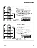
FIELD WIRING DIAGRAM FOR
SINGLE STAGE HEATING THERMOSTAT, SINGLE STAGE HEAT PUMP
NOTES:
1) For PWM (BK) enabled thermostats, cut the BK jumper
on the IFC and connect wiring.
2) Remove the factory Y1-O jumper for HP systems
for proper LED read out.
3) Y1 wiring from the thermostat must connect to Y1 of
the IFC for proper airflow and LED readout.
4) Place field supplied jumper between W1 and W2 on the
IFC. Interstage delay is factory set for 10 minutes but is field
adjustable with the Menu option in the ISD section.
5) Single stage airflow is set with the IFC Menu options
in ODU section. Select 1-1.
INTER-COMPONENT WIRING
24 V FIELD WIRING
24 V FACTORY WIRING
Furnace IFC
BK JUMPER
SEE NOTE 1

