background image

12

Propane Installation Code which requires the vent system components 

be certified to ULC S636.

This water heater has been design certified to be vented with PVC pipe 

certified  and  marked  as  complying  with  ULC  S636. This  water  heater  is 

supplied with a 2 inch 22.5 degree termination elbow that is a special fitting 

that must be used with the appliance. Any outlet piping, fittings and glue used 

to vent this appliance that is not supplied by the manufacturer must comply 

with the ULC S636 requirements. 

PVC Materials should use ASTM D-2564 Grade Cement; CPVC Materials 

should use ASTM F-493 Grade Cement and ABS Materials should use ASTM 

D-2235 Grade Cement.

If the water heater is being installed as a replacement for an existing power 

vented heater in pre-existing venting, a thorough inspection of existing venting 

system must be performed prior to any installation work. Verify that correct 

material as detailed above has been used, and that the minimum or maximum 

vent lengths and terminal location as detailed in this manual have been met. 

Carefully inspect the entire venting system for any signs of cracks or fractures, 

particularly at joints between elbows and other fittings and straight runs of 

vent pipe. Check system for signs of sagging or other stresses in joints as 

a result of misalignment of any components in the system. If any of these 

conditions are found, they must be corrected in accordance with the venting 

instructions in this manual before completing installation and putting the water 

heater into service.

NOTE:  for Water Heaters in locations with high ambient temperatures (above 

100°F or 38°C) and/or insufficient dilution air, it is recommended that CPVC or 

ABS pipe and fittings (

MUST USE SUPPLIED VENT TERMINAL

) be used.

NOTE:  Stress levels in the pipe and fittings can be significantly increased by 

improper installation. If rigid pipe clamps are used to hold the pipe in place, 

or if the pipe cannot move freely through a wall penetration, the pipe may 

be directly stressed, or high thermal stresses may be formed when the pipe 

heats up and expands. Install accordingly to minimize such stresses.

VENT PIPE PREPARATION

1.  INITIAL PREPARATION


  A. Make sure the solvent cement you are planning to use is designed  

  for the specific application you are attempting.

  B. Know  the  physical  and  chemical  characteristics  and  limitations  of 


  the PVC, PVC cellular core, ABS or CPVC piping materials that you 


  are about to use.

  C. Know  the  reputation  of  your  pipe  and  cement  manufacturer  and


  their products.

  D. Know your own qualifications or those of your contractor. The solvent


  welding technique of joining PVC, PVC cellular core, ABS or CPVC


  pipe is a specialized skill just as any other pipe fitting technique.


  E. Closely supervise the installation and inspect the finished job before 


  start-up.


  F.  Contact the manufacturer, supplier, or competent consulting agency 


  if  you  have  any  questions  about  the  application  or  installation  of 


  PVC, PVC cellular core, ABS or CPVC pipe.


  G. Take the time and effort to do a professional job. Shortcuts will only 


  cause you problems and delays in start-up. The majority of failures 


  in these systems are the result of shortcuts and/or improper joining 


  techniques.

2. SELECTION OF MATERIALS

PRIMER

It is recommended that Tetrahydrofuran (THF) be used to prepare the surfaces 
of pipe and fittings for solvent welding. Do not use water, rags, gasoline or 
any other substitutes for cleaning PVC cellular core, ABS or CPVC surfaces. 
A chemical cleaner such as MEK may be used.

INSTALLATION OF VENT SYSTEM

 WARNING

THE OPTIONAL INTAKE VENTING ARRANGEMENT AND THE EXHAUST 

VENTING ARRANGEMENT MUST BE INSTALLED TO RUN DIRECTLY TO 

THE OUTDOORS AND NOT IN ANY WAY BE CONNECTED TO ANOTHER 

VENTING SYSTEM (I.E. FURNACE, DRYERS OR SPACE HEATERS). IT 

IS CRUCIAL THAT THE VENTING ARRANGEMENT BE KEPT SEPARATE 

FROM OTHER VENTING SYSTEMS. IF THIS WARNING IS IGNORED, AND 

THE SYSTEM IS VENTED INCORRECTLY, IT MAY CAUSE IMPROPER 

OPERATION, FIRE, EXPLOSION, OR ASPHYXIATION

.

1.  Plan the route of the vent system from the vent termination to the planned 

location of the appliance. Layout the total vent system to use the minimum 

of vent pipe and elbows possible.

2.  The installer may add up to a MAXIMUM OF FIFTY (50) EQUIVALENT 

FEET (15.2 m) of pipe to the exhaust venting arrangement. This addition 

of FIFTY (50) EQUIVALENT FEET (15.2 m) of pipe on both the intake 

venting arrangement and exhaust venting arrangement must include any 

3" PVC elbows which equals (5) EQUIVALENT FEET (1.5 m) of pipe.

3.  It is important that condensate not be allowed to buildup in the exhaust 

vent pipe. To prevent this from happening the pipe should be installed with 

a slight, 1/8" (3mm) per 5' (152 cm) of pipe maximum downward slope.

4.  The vent system should be supported every 5' (152 cm) of vertical run 

and every 3' (91cm) of horizontal run of vent pipe length.

Table 2.  VENT LENGTH TABLE

  Number 

3"  

3"  

        4" 


of 90° 

Minimum 

Maximum 

Maximum

  Elbows 

Pipe (Ft./M.) 

Pipe (Ft./M.)  

Pipe (Ft./M.)

  ONE (1) 

7/2 

45/13.7 

115/35

  TWO (2) 

7/2 

40/12.2 

110/33.5

  THREE (3) 

7/2 

35/10.7 

105/32

  FOUR (4) 

7/2 

30/9.1 

100/30.5

  FIVE (5) 

7/2 

--- 

     95/29


SIX (6) 

7/2 

--- 

    90/27.4

4" PVC may be used for a MAXIMUM intake of ONE HUNDRED TWENTY 

(120)  EQUIVALENT  FEET  (36.6m)  and  a  MAXIMUM  exhaust  of  ONE 

HUNDRED TWENTY (120) EQUIVALENT FEET  (36.6m).  The maximum 

number of 90° elbows with the 4" venting is six (6) on the intake and six (6) 

on the exhaust.  A 90° elbow is equal to five (5) equivalent feet (1.5m) of pipe.  

One (1) 90° elbow  is equal to  two (2) 45° elbows.  Any venting configuration 

using less than 50 equivalent feet should use 3" venting. See Table 2.

The  3"  venting  terminals  (provided)  must  be  used  with  the 


3" vent pipe. Two, approved 4" vent terminals (not provided) must be used 

with 4" vent pipe. See replacement parts list for terminals.

IMPORTANT

When multiple units are direct vented through a wall (3" or 4" venting), all intake 

vent terminals should be no lower than the highest exhaust vent terminal.

U.S. INSTALLATIONS

NOTE:  This unit can be vented using only PVC (Class 160, ASTM D-2241 

Schedule 40, ASTM D-1785 ; or Cellular Core Schedule 40 DWV, ASTM 


F-891) , Schedule 40 CPVC (ASTM F-411), or ABS (ASTM D-2661) pipe. 

The fittings, other than the 

TERMINATIONS

 should be equivalent to PVC-

DWV fittings meeting ASTM D-2665 (Use CPVC fittings, ASTM F-438 for 

CPVC pipe and ABS fittings, ASTM D-2661/3311 for ABS pipe. If CPVC or 

ABS pipe and fittings are used, then the proper cement must be used for 

all joints, including joining the pipe to the Termination  (PVC Material). PVC 

Materials should use ASTM D-2564 Grade Cement; CPVC Materials should 

use ASTM F-493 Grade Cement and ; ABS Materials should use ASTM 


D-2235 Grade Cement. 

CANADIAN INSTALLATIONS

This water heater must comply with CAN/CSA B149.1 - Natural Gas and 

Summary of Contents for AHCG3/HCG3100T150

Page 1: ...ANCE LIMITED WARRANTY WARNING If the information in these instructions is not followed exactly a fire or explosion may result causing property damage personal injury or death Do not store or use gasoline or other flammable vapors and liquids in the vicinity of this or any other appliance WHAT TO DO IF YOU SMELL GAS Do not try to light any appliance Do not touch any electrical switch do not use any...

Page 2: ...lation Code and CSA C22 1 the Canadian Electrical Code All documents are available from the Canadian Standards Association 8501 East Pleasant Valley Road Cleveland OH 44131 NFPA documents are also available from the National Fire Protection Association 1 Batterymarch Park Quincy MA 02269 FOREWORD HIGH EFFICIENCY AHCG3 HCG360T120 thru AHCG3 HCG3100T250 ROUGH IN DIMENSIONS Table 1 RECOVERY CAPACITIE...

Page 3: ...ERATURE CONTROL TABLE OF CONTENTS ROUGH IN DIMENSIONS 2 FOREWORD 2 FEATURES 3 4 Water Temperature Control 3 High Limit Switch E C O 4 Dishwashing Machine Requirement 4 Circulating Pump 5 INSTALLATION INSTRUCTIONS 4 12 Required Ability 6 Insulation Blankets 6 Locating The Heater 5 Clearances 5 Hard Water 6 Air Requirements 6 Mechanical Exhausting of Room Air 6 Unconfined Space 6 Confined Space 6 Ch...

Page 4: ...pressures above 25 pounds per square inch 173 Kpa or below 15 pounds per square inch 103 Kpa will result in improperly sanitized dishes Where pressures are high a water pressure reducing or flow regulating control valve should be used in the 180 F 82 C line to the dishwashing machine and should be adjusted to deliver water between these limits The National Sanitation Foundation also recommends cir...

Page 5: ... sometimes installed in locations where leakage may result in property damage even with the use of a drain pan piped to a drain However unanticipated damage can be reduced or prevented by a leak detector or water shut off device used in conjunction with a piped drain pan These devices are available from some plumbing supply wholesalers and retailers and detect and react to leakage in various ways ...

Page 6: ...BBER ISOLATION PIPE HANGERS ARE USED THIS PREVENTS ANY VIBRATIONS FROM BEING TRANSMITTED INTO THE LIVING SPACES HARD WATER Where hard water conditions exist water softening or the threshold type of water treatment is recommended This will protect the dishwashers coffee urns water heaters water piping and other equipment See MAINTENANCE section for details of tank cleanout procedure AIR REQUIREMENT...

Page 7: ...ntally vented gas fueled heating appliance or equipment The sign shall read in print size no less than one half 1 2 inch in size GAS VENT DIRECTLY BELOW KEEP CLEAR OF ALL OBSTRUCTIONS INSPECTION The state or local gas inspector of the side wall horizontally vented gas fueled equipment shall not approve the installation unless upon inspection the inspector observes carbon monoxide detectors and sig...

Page 8: ... U S POWER VENT CANADIAN POWER VENT FIGURE 5b CAUTION TO PREVENT EXHAUSTING PRODUCTS FROM CIRCULATING TO THE AIR INTAKE IN WINDY COLD AREAS THE MAXIMUM PRACTICAL DISTANCE BETWEEN THESE TWO TERMINALS IS RECOMMENDED ...

Page 9: ...U S DIRECT VENT CANADIAN DIRECT VENT FIGURE 6b CAUTION TO PREVENT EXHAUSTING PRODUCTS FROM CIRCULATING TO THE AIR INTAKE IN WINDY COLD AREAS THE MAXIMUM PRACTICAL DISTANCE BETWEEN THESE TWO TERMINALS IS RECOMMENDED ...

Page 10: ... LOCATION MUST BE FOLLOWED 1 The intake vent terminal and the exhaust vent terminal must terminate on the same exterior wall and must be located at a minimum of 24 61cm from the vertical centerline of the exhaust vent terminal see Figure 9 In colder climates increasing the 24 61cm minimum will reduce possibility of frost over from side winds blowing exhaust vapors to the air intake of the direct v...

Page 11: ...e the same side of roof 4 The center line of the intake vent termination and the center line of the exhaust vent termination must be no closer than 24 61cm 5 The intake vent terminal and the exhaust vent terminal must be oriented facing downward and the same direction The specifications are displayed in Figure 10 11 NOTE Exhaust vent terminal is installed using the same procedure INSTALLATION SEQU...

Page 12: ...s recommended that Tetrahydrofuran THF be used to prepare the surfaces of pipe and fittings for solvent welding Do not use water rags gasoline or any other substitutes for cleaning PVC cellular core ABS or CPVC surfaces A chemical cleaner such as MEK may be used INSTALLATION OF VENT SYSTEM WARNING THE OPTIONAL INTAKE VENTING ARRANGEMENTAND THE EXHAUST VENTINGARRANGEMENT MUST BE INSTALLED TO RUN DI...

Page 13: ...trical contacts are normally open When the fan increases the pressure in the burner the pressure switch will allowtheelectricalcontactstoclose Thepressureswitchisconnectedtotheburner tapbyapieceoftygontubing Thistubingmustbeconnectedinorderfortheswitch tochangetheelectricalcontacts Thecontrollerrequiresthattheelectricalcontacts on this air flow switch be open before it will allow the blower to com...

Page 14: ...DANCE WITH RECOMMENDATIONS OF SERVING GAS SUPPLIERS REFER TO THE NATIONAL FUEL GAS CODE FIGURE 13 CONNECTION OF GAS PIPE 1 When connecting gas pipe to unit apply wrench to flange only Note Do not use wrench on gas valve or gas bracket See Figure 14a b c 2 PERFORMTHE GAS LEAKTESTANYTIME WORK IS DONE ONAGAS SYSTEM TOAVOID THE POSSIBILITY OF FIRE OR EXPLOSION WITH PROPERTY DAMAGE PERSONAL INJURY OR L...

Page 15: ...LVE This heater is equipped with an approved temperature and pressure relief valve ASME ratings cover pressure relief CSA ratings cover release rate with temperature actuation FOR SAFE OPERATION OF THE WATER HEATER THE RELIEF VALVE S MUST NOT BE REMOVED OR PLUGGED In addition to the appliance relief valve each remote storage tank which may be used in conjunction with this appliance shall also be i...

Page 16: ...Supply Voltage is reversed the controller will not sense flame Verify polarity before connecting the unit 3 This unit may never be connected to any existing heating system or component s previously used with non potable water heating appliance 4 When the system requires water for space heating at temperatures higher than required for domestic water purposes a tempering valve must be installed Plea...

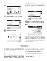
Page 17: ...ay the desktop screen if there are no active faults or warnings An example of this screen is shown to the right The first temperature on this screen is the temperature of the water inside the tank The second temperature on this screen is the Operating Set Point The Operating Set Point is the temperature at which the water heater will maintain the water inside the tank The third line on the screen ...

Page 18: ...nu DISPLAY ACTION From the Main Menu press Select to enter the Temperatures screen DISPLAY 2 Operating States In the main desktop screen there are some specific Operating States that are indicated on the status line These are summarized below ACTION Press Change then use the UP and DOWN buttons to change the Set Point Note This procedure can also be used to change the Differential The Tank Upper a...

Page 19: ...can occur during operation These are Warnings and Faults Warnings This is a non safety related condition that the control has detected that may cause the water heater to operate in a less than optimal condition but does not pose a safety concern NOTE When these conditions occur continued heating cycles will continue and the heater will attempt to regulate the water in the tank to the Operating Set...

Page 20: ...ation about the water heater and the current status of specific conditions can be found INSTALLATION OR SERVICE OF THIS WATER HEATER REQUIRES ABILITY EQUIVALENT TO THAT OF A LICENSED TRADESMAN IN THE FIELD INVOLVED PLUMBING AIR SUPPLY VENTING GAS SUPPLY AND ELECTRICAL WORK ARE REQUIRED Before attempting start up thoroughly study and familiarize yourself with the exact sequence of operation and all...

Page 21: ...er and the inlet pressures confirmed simply turn the switch on and observe operation Cycle the unit off and on several times to ensure proper operation OPERATING INSTRUCTIONS IMPORTANT IT IS RECOMMENDED THAT A QUALIFIED SERVICE TECHNICIAN PERFORM THE INITIAL FIRING OF THE HEATER AT THIS TIME THE USER SHOULD ASK THE TECHNICIAN ANY QUESTIONS IN REGARD TO THE OPERATION AND MAINTENANCE OF THE UNIT CAU...

Page 22: ...3100T150 NaturalGas AHCG3 HCG3100T 199thruAHCG3 HCG3100T250 PropaneGas AHCG3 HCG3100T 199thruAHCG3 HCG3100T250 Maximum Gas Supply Pressure 10 5 WC 2 59kpa 14 0 WC 3 45kpa 10 5 WC 2 59kpa 14 0 WC 3 45kpa Nominal Gas Supply Pressure 7 0 WC 1 74Kpa 11 0 WC 2 74Kpa 7 0 WC 1 74Kpa 11 0 WC 2 74Kpa Minimum Gas Supply Pressure 4 8 WC 1 18 Kpa 8 5 WC 2 08 Kpa 4 8 WC 1 18 Kpa 8 5 WC 2 08 Kpa Manifold Pressu...

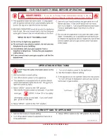
Page 23: ...R YOUR SAFETY READ BEFORE OPERATING WARNING If you do not follow these instructions exactly a fire or explosion may result causing property damage personal injury or loss of life AHCG3 HCG360T120 MODELS ONLY ...

Page 24: ... OPERATING WARNING If you do not follow these instructions exactly a fire or explosion may result causing property damage personal injury or loss of life AHCG3 HCG3100T150 MODELS ONLY OPERATING INSTRUCTIONS TURN OFF GAS TO APPLIANCE ...

Page 25: ...TRUCTIONS TURN OFF GAS TO APPLIANCE FOR YOUR SAFETY READ BEFORE OPERATING WARNING If you do not follow these instructions exactly a fire or explosion may result causing property damage personal injury or loss of life OPERATING INSTRUCTIONS TURN OFF GAS TO APPLIANCE ...

Page 26: ...ay also require draining the heater 1 Turn off the heater electrical disconnect switch 2 Close the cold water inlet valve to heater 3 Open a nearby hot water faucet to vent the system 4 Open the heater drain valve 5 If the heater is being drained for an extended shutdown it is suggested the drain valve be left open during this period Follow FILLING instructions when restoring hot water service SED...

Page 27: ...usly it may be due to thermal expansion of water in a closed water supply system or it may be due to a faulty relief valve Thermal expansion is the normal response of water when it is heated In a closed system thermal expansion will cause the system pressure to build until the relief valve actuation pressure is equaled Then the relief valve will open allowing some water to escape slightly lowering...

Page 28: ...N OF WATER IN THE HOT WATER SYSTEM MUST BE PROVIDED NOTE CONNECT RETURN LINE FROM HOT WATER CIRCULATING LOOP IF USED TO COLD WATER INLET LINE PIPE TO OPEN DRAIN INSTALL IN ACCORDANCE WITH LOCAL CODES INSTALLATION DIAGRAMS ONE TEMPERATURE ONE HEATER VERTICAL STORAGE TANK FORCED CIRCULATION WITH OR WITHOUT BUILDING RECIRCULATION CAUTION If the plumbing requires the use of pipes with dissimilar mater...

Page 29: ... PAGE 4 IF HIGHER PREHEAT TEMPERATURES ARE NECESSARY TO OBTAIN ADEQUATE BOOSTER OUTPUT ADD AN ANTI SCALD VALVE FOR HOT WATER SUPPLIED TO FIXTURES CAUTION IF BUILDING COLD WATER SUPPLY HAS A BACK FLOW PREVENTER CHECK VALVE OR WATER METER WITH CHECK VALVE PROVISIONS FOR THERMAL EXPANSION OF WATER IN THE HOT WATER SYSTEM MUST BE PROVIDED CAUTION If the plumbing requires the use of pipes with dissimil...

Page 30: ... TEMPERATURE SETTING SHOULD NOT EXCEED SAFE TEMPERATURE AT FIXTURES SEE WATER TEMPERATURE CONTROL WARNING ON PAGE 4 IF HIGHER PREHEAT TEMPERATURES ARE NECESSARY TO OBTAIN ADEQUATE BOOSTER OUTPUT ADD AN ANTI SCALD VALVE FOR HOT WATER SUPPLIED TO FIXTURES CAUTION If the plumbing requires the use of pipes with dissimilar material for example steel and copper use dielectric unions to preventanelectro ...

Page 31: ...ITH LOCAL CODES TWO TEMPERATURE TWO HEATERS ONE PRE HEATER ONE BOOSTER HEATER WITH OR WITHOUT BUILDING RECIRCULATION DANGER TEMPERATURE SETTING SHOULD NOT EXCEED SAFE TEMPERATURE AT FIXTURES SEE WATER TEMPERATURE CONTROL WARNING ON PAGE 4 IF HIGHER PREHEAT TEMPERATURES ARE NECESSARY TO OBTAIN ADEQUATE BOOSTER OUTPUT ADD AN ANTI SCALD VALVE FOR HOT WATER SUPPLIED TO FIXTURES CAUTION If the plumbing...

Page 32: ...SHOULD NOT EXCEED SAFE TEMPERATURE AT FIXTURES SEE WATER TEMPERATURE CONTROL WARNING ON PAGE 5 IF HIGHER PREHEAT TEMPERATURES ARE NECESSARY TO OBTAIN ADEQUATE BOOSTER OUTPUT ADD AN ANTI SCALD VALVE FOR HOT WATER SUPPLIED TO FIXTURES CAUTION IF BUILDING COLD WATER SUPPLY HAS A BACK FLOW PREVENTER CHECK VALVE OR WATER METER WITH CHECK VALVE PROVISIONS FOR THERMAL EXPANSION OF WATER IN THE HOT WATER ...

Page 33: ...ts with the higher water flow may have a shortened life Dimensions shown are for minimum space occupied by the water heaters assemblies Space for the venting system and unit servicing must be added CAUTION If the plumbing requires the use of pipes with dissimilar material for example steel and copper use dielectric unions to preventan electro galvanicaction between the piping components with dissi...

Page 34: ...lve is tightly closed Also check the cleanout opening for leakage 2 The apparent leakage may be condensation which forms on cool surfaces of the heater and piping 3 If the outlet of the relief valve is leaking it may represent Excessive water pressure Excessive water temperature Faulty relief valve Excessive water pressure is the most common cause of relief valve leakage It is often caused by a cl...

Page 35: ...repurge portion of the ignition cycle due to the location of the gas orifice MOTOR RUNS BURNER LIGHTS MOMENTARILY THEN LOCKS OUT 1 Reset the appliance two more times to ensure that all of the air has been purged from the gas line 2 If the burner lights momentarily but does not sustain ignition verify that the inlet pressure is not greater than 10 5 WC 2 59 kPa for natural gas and 14 0 WC 3 45 kPa ...

Page 36: ... of controlling thermal expansion is also installed at the heater s and operational at all times The relief valve installed on the heater is not an acceptable method 4 SERVICE AND REPAIR EXPENSES Under the limited warranty the warrantor will provide only a replacement water heater or part thereof The owner is responsible for all other costs Such costs may include but are not limited to a Labor cha...

Page 37: ...37 NOTES ...

Page 38: ...38 NOTES ...

Page 39: ...39 NOTES ...

Page 40: ...40 PO Box 1597 500 Princeton Road Johnson City TN 37605 Phone 1 800 456 9805 www americanwaterheater com ...

Reviews: