background image

23

Replacement Parts

IMPORTANT:

 The following maintenance procedures are 

for the Flame Guard

 Safety System components and 

should be performed by a qualified person.
Replacement parts may be ordered through your plumber 
or the local distributor. Parts will be shipped at prevailing 
prices and billed accordingly. When ordering replacement 
parts, always have the following information ready:
1.  model, serial, and product number
2.  type of gas
3. item 

number

4. parts 

description

See pages 31-32 for a list of available repair parts.

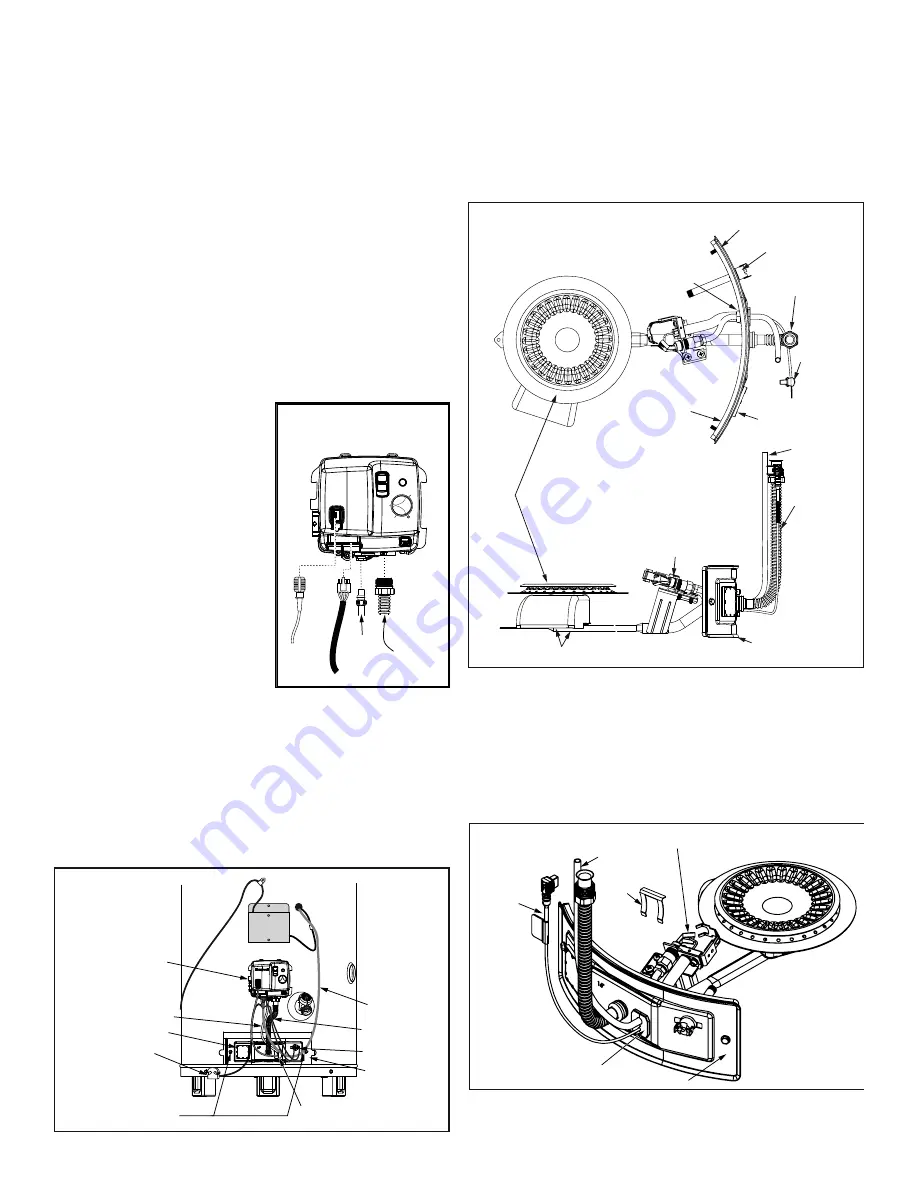
Removing the Manifold Assembly

1.  Turn off the gas to the water heater at the manual 

shut-off valve (Figure 5).

2.  Move the ON/OFF switch on the gas control valve/

thermostat to the “OFF” 
position to turn off the water 
heater. 
(Figure 22).

3.  Remove the outer door.
4.  Remove the two screws 

(1/4” nut driver) securing 
the manifold door assembly 
to the combustion chamber 
(Figure 28).

5.  Disconnect the pilot tube 

(7/16” wrench), the igniter 
wire, and manifold tube  
(3/4” wrench) at the gas 
control valve/thermostat. 
Also use needle nose pliers 
to disconnect the yellow 
TCO wire leads from the thermal switch on the manifold 
door.  

NOTE:

 L.P. Gas systems use reverse (left-hand) 

threads on the manifold tube. 

6.  Grasp the manifold tube and push down slightly to free 

the manifold and pilot tube.

7.  Carefully remove the manifold assembly from the 

burner compartment.  


NOTE:

 Be sure not to damage internal parts. 

Removing the Burner from the 
Manifold Assembly

Natural Gas Burner (Low Nox) & L.P. Burner

1.  Take off the burner by removing the two (2) screws lo-

cated underneath the burner.

2.  Check the burner to see if it is dirty or clogged. The burner 

may be cleaned with soap and hot water (Figure 29).

Pilot 

Tube

Manifold 

Tube

Igniter
Wire

Figure 27
Gas Control Valve/
Thermostat

Wiring Harness

ON

OFF

STATUS

A


B     C


   •


 •

VER

Y

HOT

HOT

LOW

VAC

Figure 29
Natural gas (Low NOx) and L.P. 
Burner Assembly

Thermal Switch

Viewport

Manifold Door Assembly

Manifold Door
Gasket

Manifold Tube

Manifold Component

Block

Igniter Wire

Screws

Burner

Manifold Tube

Manifold Door
Assembly

Pilot Tube

Pilot/Igniter - Flame
Sensor Assembly

Figure 28
Burner Assembly
Removal

Manifold Screw (2)

Manifold Component Block

Manifold Door

Thermal Switch

Pilot Tube

Manifold Tube

Viewport

Wiring
Harness

Gas Control Valve/
Thermostat

FV Sensor

Replacing the Pilot/Igniter - Flame 
Sensor Assembly

1.  Remove the manifold assembly as directed previously.
2.  Lift the retainer clip straight up from the back of 

the manifold component block (using a flat-blade 
screwdriver), then remove the manifold component 
block from the manifold door (Figure 30).

3.  Using a 7/16” wrench, loosen the nut securing the pilot 

tube to the pilot assembly. 

Figure 30 
Manifold Component
Block Assembly

Pilot/Igniter-Flame Sensor Assembly

Manifold Component
Block

Pilot Tube

Igniter
Wire

Manifold Door

Retainer
Clip

Summary of Contents for Residential Gas Water Heater

Page 1: ...erty damage personal injury or death INSTALLER AFFIX THESE INSTRUCTIONS TO OR ADJACENT TO THE WATER HEATER OWNER RETAIN THESE INSTRUCTIONS AND WARRANTY FOR FUTURE REFERENCE RETAIN THE ORIGINAL RECEIPT AS PROOF OF PURCHASE Table of Contents 2 Residential Gas Water Heater with the Flame Guard Safety System To obtain technical warranty or service assistance during or after the installation of this wa...

Page 2: ...nstructions are not followed Important Instructions Do not use this appliance if any part has been under water Immediately call a qualified person Water heaters sub jected to flood conditions or any time the gas controls main burner or pilot have been submerged in water require replacement of the entire water heater Hydrogen gas can be produced in a hot water system that has not been used for a lo...

Page 3: ...You or future users of this water heater will need it for future reference Service to the Flame Guard Safety System should only be performed by a qualified person Examples of a qualified person include licensed plumbers authorized gas company personnel and authorized service personnel IMPORTANT The manufacturer and seller of this water heater will not be liable for any damages injuries or deaths c...

Page 4: ... flammable vapors in the area This will not prevent a possible fire explosion if the igniter activates and flammable vapors have accumulated in the combustion chamber with the pilot light off If you suspect a flammable vapor incident has occurred do not use this appliance Do not attempt to light this appliance if you suspect flammable vapors have accumulated inside or outside the appliance Immedia...

Page 5: ...ors of the structure Due to the normal corrosive action of the water the tank will eventually leak after an extended period of time Also any external plumbing leak including those from improper installation may cause early failure of the tank due to corrosion if not repaired If the homeowner is uncomfortable with making the repair a qualified person should be contacted A suitable metal drain pan s...

Page 6: ... height Figure 4 Gas Piping Gas Pressure IMPORTANT The gas supply pressure must not exceed the maximum supply pressure as stated on the water heater s data plate The minimum supply pressure is for the purpose of input adjustment Gas Pressure Testing IMPORTANT This water heater and its gas connection must be leak tested before placing the appliance in operation If the code requires the gas lines to...

Page 7: ...fresheners paint and varnish removers refrigerants and many other commercial and household products When burned vapors from these products form highly corrosive acid compounds These products should not be stored or used near the water heater or air inlet Combustion and ventilation air requirements are determined by the location of the water heater The water heater may be located in either an open ...

Page 8: ...nput of all gas utilization equipment i e water heaters furnaces clothes dryers etc and the method by which the air is provided The BTU HR input can be found on the water heater data plate Additional air can be provided by two methods 1 All air from inside the building 2 All air from outdoors Figure 6 Opening Locations Confined Spaces 12 maximum Permanent openings to the outside or additional room...

Page 9: ...e opened automatically during equipment operation Keep louvers and grilles clean and free of debris or other obstructions Table 4 Minimum Free Area of Permanent Openings for Ventilation and Combustion Air Supply All Air from Outdoors Only Based on the total BTU HR input rating for all utilizing equip ment within the confined space Opening Source Minimum Free Area Per Opening sq in Reference Drawin...

Page 10: ...nes in these instructions for sizing a vent pipe system If a transition to a larger vent size is required the vent transition connection must be made at the draft hood outlet Vent Connectors 1 Type B Double wall U L Listed Vent Pipe 2 Single wall Vent Pipe Maintain the manufacturer s specified minimum clearance from combustible materials when using type B double wall vent pipe Vent connectors made...

Page 11: ... gas vent must be terminated in a vertical position to facilitate the removal of the burnt gases An unused chimney flue or masonry enclosure may be used as a passageway for the installation of a gas vent Figure 15 Common combined venting is allowable with vertical type B vent systems and lined masonry chimneys as long as proper draft for the water heater is established under all conditions of oper...

Page 12: ...ture of the water by mixing cold and hot water and are readily available for use 4 If installing the water heater in a closed water system install an expansion tank in the cold water line as specified under Closed System Thermal Expansion section 5 Install a shut off valve in the cold water inlet line It should be located close to the water heater and be easily accessible Know the location of this...

Page 13: ...erson include licensed plumbers authorized gas company personnel and authorized service personnel Do not plug valve Do not remove valve Failure to follow these instructions can result in death or explosion WARNING As water is heated it expands thermal expansion In a closed system the volume of water will grow As the volume of water grows there will be a corresponding increase in water pressure due...

Page 14: ...distortion Must be installed to allow complete drainage of both the valve and discharge line T P Relief Valve and Pipe Insulation Some Models 1 Locate the temperature and pressure relief valve on the water heater also known as a T P relief valve See Figure 18 2 Locate the slit running the length of the T P relief valve insulation 3 Spread the slit open and fit the insulation over the T P relief va...

Page 15: ...ee of corrosive elements and flammable vapors Fresh air openings sized correctly with consideration given to the blocking effect of louvers and grilles Ductwork is the same cross sectional area as the openings Vent Pipe System Check for proper drafting at the water heater draft hood Refer to the Checking the Draft section of this manual for the test procedure If the procedure shows insufficient dr...

Page 16: ... a qualified service technician to inspect the appliance Water heaters subjected to a flammable vapors ignition will show a discoloration on the air intake grid bottom of combustion chamber and require replacement of the entire water heater 2 Move the ON OFF switch on the Gas Control Valve Thermostat to the OFF position WARNING If you do not follow these instructions exactly a fire or explosion ma...

Page 17: ...e 20 Match Relief Opening Draft Hood Burn Hazard Do not touch vent Doing so can result in burns WARNING Burner Flames Inspect the burner flames through the viewport and compare them to the drawings in Figure 21 A properly operating burner should produce a soft blue flame Blue tips with yellow inner cones are satisfactory The tips of the flame may have a slight yellow tint The flame should not be a...

Page 18: ... second instantaneous 45 minutes 5 minutes 25 seconds 5 seconds 2 seconds 1 seconds U S Government Memorandum C P S C Peter L Armstrong Sept 15 1978 Gas Control Temperature Knob Igniter 120 F Mark Gas Control Temperature Knob ON OFF STATUS A B C VERY H O T HOT LOW On Off Switch VAC Status Light VAC A B C VERY H O T HOT LOW Figure 22 Gas Control Valve Thermostat Settings NOTE During low demand peri...

Page 19: ...ace all parts and panels before operating Failure to do so can result in death or electrical shock DAMPER FLAME SENSOR IGNITER GAS CONTROL VALVE THERMOSTAT 4 3 2 1 3 2 1 6 5 4 FV SENSOR TEMPERATURE CUT OFF SWITCH FLUE DAMPER TRANSFORMER 1 2 3 4 5 6 BL RD YL YL BN 24VAC V 24VAC BK 120VAC WH 120VAC GR BK 24VAC HOT WH 24VAC NEUTRAL BL RD BL RD YL YL BK 24VAC HOT WH 24VAC NEUTRAL YL 24VAC YL 24VAC TRA...

Page 20: ...eat alternates bright dim Call for Heat No fault conditions One Flash three second pause Low Flame Signal control continues to operate Two Flash three second pause End Switch Failed Closed Three Flash three second pause End Switch Failed Open or TCO Limit Lockout Four Flash three second pause ECO Limit Lockout Five Flash three second pause Flame Out of Sequence Six One Flash three second pause Sof...

Page 21: ...or to resetting the switch Contact the Product Service and Support Department for service information at 1 877 817 6750 A temperature limit switch or ECO Energy Cut Off sensor located in the gas control valve thermostat is used to shut off the water heater if the water temperature exceeds 189 F 87 C The Diagnostic Status Light will flash a code indicating an Overheat Failure 4 Flashes See Operatin...

Page 22: ...structed Build up of soot and carbon on the main burner and pilot burner Check for a soft blue flame Leaking or damaged water and gas piping Presence of flammable or corrosive materials in the installation area Presence of combustible materials near the water heater After servicing this water heater check to make sure it is working properly See Operating Your Water Heater section of this manual IM...

Page 23: ...manifold assembly from the burner compartment NOTE Be sure not to damage internal parts Removing the Burner from the Manifold Assembly Natural Gas Burner Low Nox L P Burner 1 Take off the burner by removing the two 2 screws lo cated underneath the burner 2 Check the burner to see if it is dirty or clogged The burner may be cleaned with soap and hot water Figure 29 Pilot Tube Manifold Tube Igniter ...

Page 24: ...of the pilot bracket use pliers to hold the pilot assembly bracket while loosening the pilot nut 4 Pull the pilot tube from the pilot assembly Figure 31 IMPORTANT Be careful not to bend or alter the position of the pilot assembly components 5 Use a screwdriver to remove the screws securing the Pilot Igniter Flame Sensor Assembly Keep the screws for reattachement 6 Using the old pilot pilot tube as...

Page 25: ...e two screws which secure the manifold assembly door to the combustion chamber and tighten securely There should be no space between the gasket part of the manifold door and combustion chamber IMPORTANT Do not operate the water heater if the door gasket does not create a seal between the manifold door and the combustion chamber 6 Reconnect the yellow wire leads to the thermal switch Figure 27 the ...

Page 26: ...ter before lighting and activating the water heater Follow the Lighting Instructions on page 16 With the burner lit check the gas control valve thermostat supply line manifold component block manifold tube and pilot tube connections for leaks Check for leaks by brushing on an approved noncorrosive leak detection solution Bubbles forming indicate a leak Correct any leak found IMPORTANT All leaks mu...

Page 27: ...ed hot water 1 Provide ventilation to water heater Check flue way flue baffle and burner 2 Clean flue locate source and correct 3 Check with gas utility company 4 Replace thermostat 5 Install adequate heater 6 Advise customer DRIP FROM RELIEF VALVE 1 Excessive water pressure 2 Heater stacking 3 Closed water system 1 Use a pressure reducing valve and relief valve 2 Lower the thermostat setting 3 Se...

Page 28: ... If any connections are found to be damaged consult the replacement parts list on page for the appropriate replacement After any connection problems are fixed restart the water heater by following the lighting instructions on page 16 If the problem persists replace the damper Three Flash three second pause End Switch Failed Open or TCO Limit Lockout Turn the power switch on the gas control valve t...

Page 29: ...ctrode flame sense rod replace the igniter pilot assembly Follow the directions on page 25 to re install the burner assembly into the combustion chamber Follow the instructions for lighting on page 16 If the problem persists contact a certified service representative Six Four Flash three second pause Soft Lockout Flame out of Sequence Sensed Turn the power switch on the gas control valve to the OF...

Page 30: ...n Valve Open Is Main Flame Sensed Is Demand for Heat Satisfied Pilot Main Valve De Energize Is Flame Sensed Damper Energizes and Closes Will not light 8 4 flash error code See Corrective Action Table on page 28 N Will not light 8 4 flash error code See Corrective Action Table on page 28 N Will not light 8 4 flash error code See Corrective Action Table on page 28 N Will not light 8 4 flash error co...

Page 31: ...S CONTROL VALVE THERMOSTAT 11 OUTER DOOR 12A STP SPARK TO PILOT PILOTASSEMBLY KIT 12B STP SPARK TO PILOT PILOTASSEMBLY KIT L P 13A BURNER Natural Gas Low Nox 13B BURNER L P 14A BURNER ASSEMBLY 14B BURNER ASSEMBLY L P Burner 15 MANIFOLD COMPONENT BLOCK 16 MANIFOLD DOOR GASKET 17 VIEWPORT ASSEMBLY 18 TRANSFORMER ASSEMBLY KIT 19 FV SENSOR KIT 20 FV SENSOR KIT WITH BRACKET 21 FV WIRE HARNESS 22 MAIN W...

Page 32: ...ifold tube gasket door pilot igniter flame sensor assembly manifold component block with retainer clip thermal switch and pilot tube Natural Gas Low Nox Item 14B Burner assembly which contains the manifold tube gasket door pilot igniter flame sensor assembly manifold component block with retainer clip thermal switch and pilot tube L P Gas Item 15 Contains manifold component block and retainer clip...

Reviews: