INDEX
A. TIM-615: GENERAL OVERVIEW
1) LCD Display
2) User Buttons
3) Measurement Chamber
4) Batteries
B. INSTALLATION
C. DAILY USE
D. CALIBRATION
1) Definitions
2) Reasons to Calibrate
3) Calibration Procedure
4) Display the K Factor & Restoring the
Factory K Factor
5) In-Field Calibration
6) Direct Calibration of the K Factor
E. UNIT OF MEASURE SETUP
F. METER MAINTENANCE
G. TROUBLESHOOTING GUIDE
H. PARTS BREAKDOWN AND SPECIFICATIONS
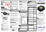
A. AMERICAN LUBRICATION TIM-615: GENERAL OVERVIEW
TIM-615 is an electronic digital oval-gear meter, designed for precise
measuring of oil and other liquids that are compatible with the
materials found in the meter. The TIM-615 features a non-volatile
memory for storing calibration and dispensing data in the event of
a complete power loss. The meter is unique in that the electronic
section is completely isolated from the fluid section. This means that
the electronics can be easily field replaced while the meter is still
installed in-line using a replacement electronics “head”.
1) LCD Display
The “LCD” of the TIM-615 features two numerical registers and
various symbols that are displayed only when required.
Batch register indicates volume dispensed
Battery charge Indicator
Calibration Mode
Total register; display can show (2) different totals,
one which is resettable and one that is non-
resettable.
Total multiplication factor ( x10 or x100 )
Total type (TOTAL / RESET TOTAL)
Total unit of measurement (Gal=Gallons, L=Liters)
Batch unit of measurement (Qts=Quarts, Pts=Pints,
L=Liters, Gal=Gallons
2) User Buttons
The TIM-615 meter features two buttons (RESET and CAL )
which individually perform two main functions and when pressed
at the same time together perform secondary functions. The
functions are:
For the RESET button, resetting the batch register and the
resettable totalizer.
For the CAL button, entering meter calibration mode.
Pressing RESET and CAL together enters the configuration
mode where the desired unit of measurement can be set.
3) Fluid Chamber
The measurement chamber is located in the lower part of the
meter. It features a 1/2” NPT(F) inlet and outlet. The cover on the
bottom provides access to the chamber for contaminate cleaning.
Inside the chamber are two oval gears that generate electrical
pulses which are counted by the microprocessor. By applying a
calibration factor, the microprocessor translates the pulses into
units of measurement, displayed on the batch and total registers
of the LCD. All TIM-615’s are factory set with a calibration factor
(FACTORY K FACTOR) equal to 1,000.
4
5 6
8
7
1
2
3
2. Reasons to Calibrate
The TIM-615 is supplied with a factory calibration that ensures
precise measuring in most operating conditions. Meter accuracy
might be compromised when dispensing fluids like low-viscosity
automatic transmission fluid or high-viscosity gear oils. The
meters’ accuracy also might be compromised when operating at
flow rates that are close to the minimum or maximum.
When the meter’s accuracy is less than ideal, user calibration can
be performed to better suit the actual conditions in which the TIM-
615 is required to operate.
3. Calibration Procedure
Two procedures are available for changing the Calibration
Factor:
Dispensing Calibration, performed by means of a dispensing
operation.
Direct Calibration, performed by directly changing the
calibration factor inside the meter.
The calibration phases can be entered (by keeping the CAL button
pressed for a few seconds) to:
Display the current user calibration factor
Return to factory calibration (Factory K Factor) after a previous
calibration by the user
Change the calibration factor using one of the two previously
indicated procedures.
During calibration, the batch and total dispensed quantities
indicated
on the display screen take on different meanings
according to the calibration procedure phase.
In calibration mode, the TIM-615 cannot be used for normal
dispensing operations. During the calibration process, the totals
are not increased.
4. Displaying the K Factor & Restoring the Factory K Factor
By pressing the CAL button while the meter is in standby mode,
one of two display pages will appear showing the current
calibration factor.
The following display page will appear if
calibration has been performed or the meter
has been restored to factory calibration.
The word “FACT” (abbreviation for “factory”)
indicates that the factory calibration factor is
being used.
This display page will appear if a calibration
has been made by the user. It shows the
current used calibration factor (in the example
0.998) and the word “USER” (indicating that
the user calibration factor is being used)
The flow chart shows
the switch-over logic
from one display page
to another
In this condition, the
Reset button permits
switching from the
User factor to the
Factory factor.
To confirm the choice
of the calibration
factor, quickly press
the CAL button while
“USER” or “FACT”
are displayed.
After the restart cycle,
the TIM-615 uses
the calibration factor
that had just been
confirmed
5. In-Field Calibration
This procedure requires the fluid to be dispensed into a certified
graduated container. For best accuracy, perform this procedure when
the meter is installed in the system it is going to be used on.
5. In-Field Calibration (continued)
ACTION
DISPLAY
1
Make sure the meter is in standby mode
.
If you are unsure, press the REST button and wait 10
seconds.
2
Hold down the CAL button until the display reads
“CAL”.
The TIM-615 enters calibration mode, shows <<CAL>> and
displays the calibration factor in use. The words “FACT” and
“USER” indicate which of the two factors (factory or user)
is currently in use.
3
Hold down the RESET button until the display reads
“FIELD”.
The TIM-615 shows “CAL” and the batch register set to
zero. The TIM-615 is ready to perform in-field dispensing
calibration.
4
Dispensing into a calibrated container.
Without pressing any buttons, start dispensing
into the graduated container.
Dispensing can be stopped and started again
at will. Continue dispensing until the level of
the fluid in the sample container has reached
the graduated area.
Make sure dispensing is correctly finished before performing
the next step.
5
Press the RESET button, and quickly release.
This tells the meter that the dispensing is finished. To
finish calibrating the meter, the value on the meter’s batch
display (example 9.800) must be adjusted to equal the
actual amount in the calibrated container. In the bottom left
part of the display an arrow appears (pointing upwards or
downwards), that shows the direction (increase or decrease)
that the value on the batch display will be changed when
performing step 7.
6
Changing the Arrows direction in the display
Quickly pressing the RESET button changes the arrows
direction in the display. This operation can be repeated to
alternate the direction of the arrow.
7
Adjusting the Batch Display Value (
The indicated value
changes in the direction indicated by the arrow)
1) The amount on the display changes one unit each
time the CAL button is pressed quickly.
2) The amount on the display changes continuously
if the CAL button is kept pressed. The speed
of change increases the longer the button is
held.
If you accidentally program the wrong value, repeat the
operation starting from step number 6
8
Saving the New Calibration Factor
Before performing this operation, double-check to make
sure the display value on the meter is the same value that is
in the calibrated container.
Press the RESET button for at least one second. The TIM-
615 calculates the new USER K FACTOR. This calculation
could require a few seconds to compute. At the end of the
calculation, the new USER K FACTOR is shown for a few
seconds.
9
Finishing
The meter will re-start and enter into the standby mode. The
meter is now programmed with the new calibration factor
and is ready to use.
Note: The calibrated USER K FACTOR is now the factor
used in the TIM-615. This will be the factor the meter will
use even after battery failure and battery replacement.
CAL BUTTON
RESET
BUTTON
LCD DISPLAY
a) For a few seconds after the RESET button is pressed.
b) During the entire dispensing stage and for five seconds after
dispensing. Once this short time has expired the TIM-615
switches to standby mode and the lower register switches
back to the non-resettable total (TOTAL).
NOTE: 6 digits are available for TOTALS, plus two
icons x 10 / x100. The increment sequence follows: 0.0
→ 99999.9 → 999999 → 100000 x 10 → 999999 x 10 →
100000 x 100 → 999999 x 100
!
!
NOTE: The TIM-615 features a non-volatile memory for
storing calibration and dispensing data. There is no
need to re-calibrate the meter in the event of power loss.
NOTE: When the Factory Factor is chosen, the old user
factor is deleted from the memory
!
1) Completely eliminate all of the air from the system before calibrat-
ing.
2) Use a certified graduated container with a minimum capacity of
5 Qts. Do not use metal or plastic oil containers typically found in
automotive shops. These are typically not accurate enough.
!
NOTE: Important steps for accurate meter calibration:
!
NOTE: Important steps for accurate meter calibration:
(continued)
3) Try to keep the flow rate constant when filling the container. Do
not trickle the flow to reach the desired level (the correct method
during the final stage is to make short top-offs at the normal
operating flow rate).
4) When oil is dispensed into a container, air gets trapped
inside the oil, making the level in the container appear
higher than it really is. After dispensing, wait a few minutes
to make sure all air bubbles are eliminated from the fluid
inside the calibration container.
4) Batteries
The TIM-615 is powered by two standard AAA 1.5V Alkaline
batteries. The batteries can be found under the face of the meter
by removing the four top screws and the protective cover.
B. INSTALLATION
The TIM-615 features two ½” NPT(F) ports. It has been designed to
be installed in any position, in a fixed in-line installation or as part
of a control handle. The meter does not have specific direction of
flow and either port can be used as inlet or an outlet. Make sure
the threaded connections do not interfere with the inside of the
measurement chamber. This can cause the gears to be damaged
and/or seize. A filter with adequate filtering capacity should always
be placed at the inlet of the meter or somewhere in the product
line onto which the TIM-615 is mounted. If solid particles enter the
measurement chamber, the gears could be damaged and/or seize.
C. DAILY USE
Below are the two normal display modes. One display page shows
the batch and resettable total registers (temporary display mode).
The other page shows the batch and non-resettable total register
(standby display mode). Changeover between these two pages
is automatic and tied to phases and times that are factory set and
cannot be changed by the user.
*The batch register is in the top of the display and indicates the
quantity dispensed since the last time the RESET button was
pressed
*The resettable total register (Reset
TOTAL), positioned in the
lower part of the display, indicates the quantity dispensed since
the last time the resettable total was reset. The resettable total
cannot be reset until the batch register has been reset. The unit of
measurement of the two total registers can be the same as the batch
register or a different unit of measure depending on the factory or
user programming choice.
*The non-resettable total register (TOTAL) can never be reset by the
user. It continues to rise for the entire operating life of the TIM-615.
*The register of the two totals (Reset TOTAL and TOTAL) share the
same line of the display. The TIM-615 is programmed to show each
of these totals at different times.
*The non-ressettable (TOTAL) page is shown in standby screen
mode
*The resettable total (Reset TOTAL) page is shown in the temporary
screen mode:
1) Resetting the Batch Register
The batch register can be reset by pressing the RESET button
only when the meter is in standby mode. Press the RESET button
to reset the batch register. After pressing the RESET button, the
LCD screen will display all the characters on the screen, and
then the screen will momentarily go blank. The screen will then
display the resettable total for 5 seconds, after which the display
will return to the standby mode screen.
2) Resetting the Resettable Total (Reset TOTAL)
Wait for the display to enter standby mode
Press the RESET button quickly. This will reset the batch
register.
After pressing the RESET button, the LCD screen will display
all the characters on the screen, and then the screen will
momentarily go blank. The screen will then display the
resettable total for 5 seconds. Hold down the Reset button for
at least one second.
The LCD screen will again display all the characters on the
screen, and then the screen will momentarily go blank. The
screen will then display the resettable total (which now should
read 0.0) for 5 seconds
D. CALIBRATION
1.
Definitions
Calibration factor or “K Factor” - this is the multiplication factor
applied by the system to the electrical pulses received, to
transform these into measured fluid units.
Factory K Factor: Factory-set default factor. It is equal to
1,000.
The Factory K Factor is based on the following operating
conditions:
User K Factor:
Customized calibration factor, meaning the K
Factor obtained from calibrating the meter.
Temporary Display Mode
Standby Display Mode
Batch Display
Actual Value
Indicated Value
Real Value
1)
2)
3)
4)
5)
6)
7)
8)
a)
b)
c)
Fluid
10W30 motor oil
Temperature:
68° F.
Flow rate:
1.3 - 6.6 gallons/min.
a)
b)
c)
d)
a)
b)
c)
a)
b)
a)
b)
c)
PRO SERIES
DIGITAL OVAL GEAR METER
TIM-615
This meter is built exclusively for American
Lubrication Equipment Corporation incorporating
numerous design ideas provided by their design team.
PRO SERIES METER
PRO SERIES METER
PRO SERIES METER
PRO SERIES METER
PRO SERIES METER
PRO SERIES METER
PRO SERIES METER
PRO SERIES METER
PRO SERIES METER
PRO SERIES METER
PRO SERIES METER
PRO SERIES METER
PRO SERIES METER
Baltimore, Md. Los Angeles, Ca.
410
-252-9300
americanlube.com
Features
Fluid Isolated from the Electronics
Field-Replaceable Electronic Head
Reliable Oval Gear Design
New AAA Ba
t
tery Lasts Longer
6 Bolt Construction
Programmable to Pts, Qts, Lts & Gals
Molded-in Shock Guard
Bulletin M0169 EN rev.1
Bulletin M0169 EN rev.1
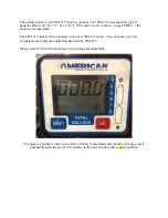
The batch register (top
row) can be reset; the total
register (bottom row)
cannot be reset (even if
you take the batteries
out).


