D. CALIBRATION (continued)
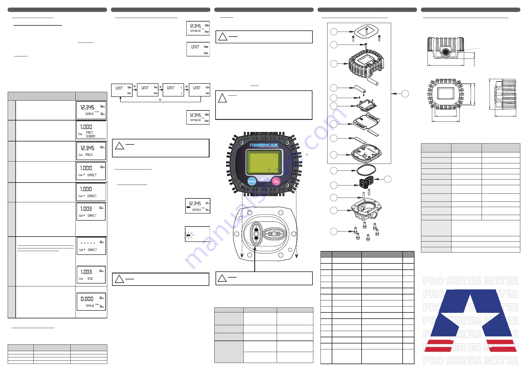
6. Direct Calibration of the K Factor
This procedure is useful if the meter is over-dispensing or under-
dispensing fluid by a known percentage. Using this method, the
correction of the USER K FACTOR must be calculated by the
operator using the following formula:
New Cal. Factor = Old Cal Factor *
( )
100 - E%
100
Example:
Error percentage found
(
E%)
- 0.3 %
CURRENT calibration factor
1.000
New USER K FACTOR
1.000 * [(100 – ( - 0.3))/100]
= 1.000 * [(100 + 0.9)/100]
= 1.003
If the TIM-615 is under-dispensing (negative error), the new
calibration factor must be higher than the old one as shown in the
example. The opposite applies if the TIM-615 is over-dispensing
(positive error).
ACTION
DISPLAY
CONFIGURATION
1
Make sure the meter is in standby mode
.
If you are unsure, press the REST button and wait 10
seconds.
2
Hold down the CAL button until the display reads
“CAL”.
The TIM-615 enters calibration mode, shows <<CAL>>
and displays the calibration factor in use. The words
“FACT” and “USER” indicate which of the two factors
(factory or user) is currently in use.
3
Hold down the RESET button until the display reads
“FIELD”.
The TIM-615 shows “CAL” and the batch register set to
zero. The TIM-615 is ready to perform in-field dispensing
calibration.
4
Hold down the RESET button until the display reads
“DIRECT”.
In the bottom left part of the display an arrow appears
(pointing upwards or downwards), that shows the direction
(increase or decrease) that the value on the batch display
will be changed when performing step 6.
5
Changing the Arrows direction in the display
Quickly pressing the RESET button changes the arrows
direction in the display. This operation can be repeated to
alternate the direction of the arrow.
6
Adjusting the Batch Display Value (
The batch display
value changes in the direction indicated by the arrow)
1) The amount on the display changes one unit each
time the CAL button is pressed quickly.
2) The amount on the display changes continuously
if the CAL button is kept pressed. The speed
of change increases the longer the button is
held.
If you accidentally program the wrong value, repeat the
operation starting from step number 5.
7
Saving the New Calibration Factor
Before performing this operation, double-check to make
sure the display value on the meter is equal to the value
you obtained using the calibration formula.
Press the RESET button for at least one second. The TIM-
615 calculates the new USER K FACTOR. This calculation
could require a few seconds to compute.
At the end of the calculation, the new USER K FACTOR is
shown for a few seconds.
8
Finishing
The meter will re-start and enter into the standby mode.
The meter is now programmed with the new calibration
factor and is ready to use.
Note: The calibrated USER K FACTOR is now the
factor used in the TIM-615. This will be the factor the
meter will use even after battery failure and battery
replacement.
E. UNIT OF MEASURE SETUP
The user can select the batch measurement unit. The choices are:
Quarts (
Qts
), Pints (
Pts
), Liters (
Lit
), and Gallons (
Gal
). The total
register unit of measurement is automatically determined based on
what is chosen for the batch measurement unit (see chart below).
Combination no.
Unit of Measurement
Partial Register
Unit of Measurement
Totals Register
1
Liters (L)
Liters (L)
2
Gallons (Gal)
Gallons (Gal)
3
Quarts (Qts)
Gallons (Gal)
4
Pints (Pts)
Gallons (Gal)
E. UNIT OF MEASURE SETUP (continued)
To choose between the 4 available combinations:
Wait for the TIM-615 to go to
Standby.
Press and hold the CAL and RESET
buttons together. Keep these pressed
until the word “UNIT” appears on the
screen. You will also see the current
units of measure (in this example Qts
& Gal).
Each quick press of the RESET
button changes the units of measure.
The chart below shows the order of
scrolling.
Press the CAL key for a few seconds
and the new unit of measurement
will be stored. The meter will re-start
and enter into the standby mode.
The meter is now programmed with
the new unit(s) of measure and is
ready to use.
F. METER MAINTENANCE
The TIM-615 was designed to require minimal maintenance. The
only maintenance required is battery replacement and cleaning the
measuring chamber.
1) Battery Replacement
The TIM-615 is supplied with two SIZE AAA, 1.5 Volt Alkaline
batteries. The meter features two low-battery alarm warnings:
When the battery charge falls
below the first level, the fixed battery
symbol appears on the LCD. In
this condition, the meter continues
to operate correctly, but the fixed
battery icon warns the user that it is
time to change the batteries.
If you continue to use the meter
without changing the batteries
the second battery alarm level will
eventually be reached, preventing
meter operation. In this condition
the battery icon will flash and will
be the only item visible on the LCD.
You must change the batteries once
the meter has reached this mode.
All dispensing data from this point
forward will not be displayed or
stored in the meter.
To change the batteries, refer to the spare parts list
in the next column while completing the following
steps:
Press reset to update all the totals.
Remove the 4 screws on the cover (item 5).
Remove the cover (item 8).
Replace the two dead batteries (item 9).
Put the cover on and re-tighten the 4 cover screws,
making sure that it has been positioned correctly.
The meter will switch on automatically and enter
into the standby mode. It is now ready to resume
normal operation.
After changing the batteries, the meter will display
the same reset total, the same non-ressettable
total and the same batch total as it did before the
batteries were changed. The meter will also use the
same calibration factor as it did before the power
outage/battery replacement.
2) Cleaning
The measuring chamber of the TIM-615 can be cleaned without
removing the unit from the dispensing nozzle or the line on which
it is installed.
To clean debris from the measuring chamber, refer to the spare
parts list on the right while completing the following steps:
Loosen the six retention screws (item 7) on the
body (item 1).
Remove the cover (item 2) and the seal (item 10)
Remove the two oval gears (item 13).
Clean where necessary. For this operation, use a
brush or pointed object such as a small screwdriver.
Be careful not to damage the body or the gears.
To reassemble the unit, carry out these steps in
the reverse order. Please pay close attention to the
note below before re-assembling the meter!
G. TROUBLESHOOTING GUIDE
Problem
Possible cause
Remedial Action
Dull LCD
Low Battery
Replace the batteries
(see section F.)
Inaccurate
Dispensing
Wrong K FACTOR
Re-calibrate
(see section D.)
Reduced or Zero
Flow Rate
Gears blocked
Clean the measurement
chamber (see section F.)
The meter does
not count, but
the flow rate is
correct
Incorrect installation of
gears after cleaning
Repeat the reassembly
procedure
(see section F.)
Possible circuit board
problem
Contact your local
American Lubrication
Equipment dealer
H. PARTS BREAKDOWN & SPECIFICATIONS
Item
Part Number
Description
Qty
1
TIM-615-1
Fluid Chamber Body
1
2
TIM-615-2
Isolation Plate
1
3
TIM-615-3
Battery Support Tray
1
4
TIM-615-4
Circuit Board
1
5
TIM-615-5
Cover Screw
4
6
TIM-615-6
Circuit Board Screw
4
7
TIM-615-7
Fluid Body Screw
6
8
TIM-615-8
Protective Cover
1
9
TIM-615-9
AAA Battery
2
10
TIM-615-10
Gasket
1
11
TIM-615-11
Cover label
1
12
TIM-615-12
Adhesive Strip
2
13
TIM-615-13
Magnetic Gear
1
14
TIM-615-14
Non-Magnetic Gear
1
15
TIM-615-15
Gear Post
2
16
TIM-615-HEAD
Replacement Meter
Head includes items 2,
3, 4, 5, 6, 8 , 9, 11 & 12
1
H. PARTS BREAKDOWN & SPECIFICATIONS (continued)
Measurement
system
Oval Gear
Resolution
(nominal)
0.005 (Quarts/Pulse)
Flow Rate
(Range)
1-26 (Quarts/Minute)
Operating pressure
(Max)
1000 (PSI)
Bursting pressure
(Min)
2000 (PSI)
Storage temperature
(Range)
-5 to 158 (°F)
Storage humidity
(Max)
95 (% RH)
Operating
temperature
(Max)
140 (°F)
Flow resistance
(at 16 quarts/min with
SAE10W motor oil at 68°F)
19 (PSI)
Viscosity
(Range)
5÷5000 (mPas)
Precision
(1 and 26 quarts/min)
±1 of value indicated after
calibration (%)
Repeatability
(Typical)
±0.3 (%)
Screen
Liquid crystals LCD
Featuring:
-
5-figure partial
-
6-figure Reset Total plus x10 / x100
-
6-figure non reset Total plus x10 / x100
Power supply
(2) 1.5 V alkaline batteries size AAA
Battery life
14,000 - 100,000 hours
Weight
.83 lbs. (including batteries)
NOTE: The Reset Total and Total will be automatically
converted to the new unit of measurement. No
new calibration is required when changing the
unit of measurement.
!
b)
a)
NOTE:
Refer to your local regulations before disposing the old
batteries.
!
1)
2)
3)
4)
c)
NOTE: Always make sure the liquid has been drained
from the meter before cleaning
.
!
NOTE: Only one of the two gears has magnets.These
gears must be inserted into the body of the meter, and
placed perpendicular to each other. To position the gears
correctly, refer to the diagram below, making sure that
the position of the gear with respect to the magnets is
observed.
If the gears are not installed correctly, the me-
ter will not work. Check that the gears are rotating freely
before closing the cover.
!
1)
2)
3)
4)
5)
6)
1)
2)
3)
4)
5)
4-1/4”
2.46”
3/
4”
2.
38
”
2.54”
1/2" NPT
3.21”
2.
55
”
3.
57
”
11
5
8
9
6
4
3
12
2
10
13
15
1
7
14
16
d)
!
NOTE:
The gear with the magnet (TIM-615-13) must be pla-
ced so that it is on the left side of the meter when assmbled


