7 //
24
P/N: 630-00047 RevB 11519
Hercules II 600 Vertical Platform Lift Install Manual | www.Ameriglide.com | 866-378-6648
PREPARING TO INSTALL
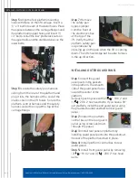
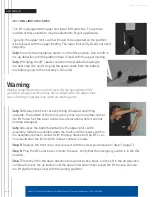
Step 6: Turn over joined rails and install the remaining two (2) joint
fasteners and firmly tighten with 3/16
"
Allen wrench. Then slide rack
pieces down to cover joint.
Step 7: Install rail brackets by loosening the screws and snapping
each bracket edge into the slot, or slide the brackets on from the top
of the rail.
When in final position, the nuts will be on the wall side.
Step 8:
A. For double rails, tighten the first rail bracket in place so that,
when turned over, the back of the bracket touches the rear of the
first step from the bottom landing. Place and tighten the second
and third brackets on the steps on each side of the rail joint,
again
so the back of the bracket touches the rear of the step. Then
place the fourth and final bracket on the last step before the top
landing, again tightening it so it touches the front of the rear of
the last step.
B. For single rails, tighten the first rail bracket in place so that,
when turned over, the back of the bracket touches the rear of the
first step from the bottom landing. Place the other rail bracket on
FINAL SITE INSPECTION
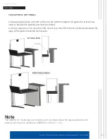
Verify the surface of the lift will mount to is smooth and level. This surface must
be made from 3,500PSI reinforced concrete with a minimum thickness of 4
"
.
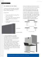
Verify that there is enough space for the lift’s footprint. Include space for the
folding access ramp, allowing 50
"
x 64
"
. Size is for 36
"
x 48
"
platform.
•
The horizontal gap between the edge of the platform and the upper
landing must be no less than ⅜
"
and no greater than ¾
"
.
•
The horizontal gap between the guard panel and any wall or barrier
must be no less than 2
"
and no greater than 3
"
.
•
The ASME A18.1 Code requires that a gate or door be installed at the
upper landing.
•
Verify that sufficient head room exists above the lift. The lift will require
6
'
8
"
of clearance above the platform floor when the lift is at the upper
landing.
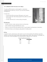
CONNECTING ELECTRICITY
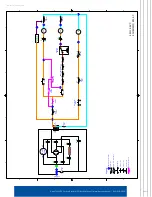
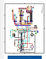
The lift requires a 120VAC 15AMP grounded, dedicated electrical outlet within
6
'
of the lift. Plug the lift directly into the power outlet. Do not plug anything else
into the same outlet as the lift.
NOTE: Follow NFPA70 National Electrical Code (NEC) adopted in your state,
county or city jurisdiction.
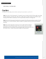
Caution
Verify that the running clearance around the lift complies with any codes for your area.
Warning
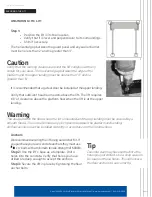
The area below the top landing edge must be covered by a smooth vertical fascia to
eliminate pinch points between the platform and landing. Requirement by ASME A18.1
safety standard for platform lifts and stairway chair lifts.
Warning
Do not ride on the lift until it has been anchored in place.
Summary of Contents for AMGHERC600-4
Page 24: ...P N 630 00047 RevB 11519 ...

