background image

16 

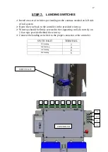
STEP 7:    SUSPENDING CARRIAGE 

The contrôler comes with jumper for landing and safety,

POWER ON controll

Turn to servicing mode with key

Lift carriage untill this mean you can actualy move carefully the carriage

in the upper direction untill the carriage lift and chain become under load.

Turn off controller

Adjust chain tension to limit the vibration of the chain under the carriage.

Summary of Contents for PRO DUMBWAITER

Page 1: ...PRO DUMBWAITER JUNE 2020 Revision 5110 Atlantic Avenue Raleigh NC 27616 info ameriglide com Ph 855 265 5691 Fax 800 791 6524 ...

Page 2: ... steps to install successfully the dumbwaiter in a building use all personal protective equipment and state of the art work methods to prevents injury electrical choc and all other danger for yourself and peoples surrounding the installation 4 Failure to comply with these procedures may compromise the conformity of the final product 5 Consult a structural engineer for load calculation and transfer...

Page 3: ...3 MAJOR COMPONENTS HEAD GUIDE RAILS LANDING SWITCH CAR CONTROLER DISCONECT DRIVE UNIT BATTERY BANK LIFTING CHAIN ...

Page 4: ...4 DRIVE UNIT CONTROLER EMERGENCY STOP BATTERY BANK DISCONNECT ...

Page 5: ...5 ...

Page 6: ...EAD 12 STEP 6 LIFTING CHAIN 13 STEP 7 SUSPENDING CARRIAGE 16 STEP 7 LANDING SWITCHES 17 STEP 8 LANDING KIT 18 STEP 8 CAB ASSEMBLY 19 STEP 9 ACCEPTANCE TESTS 20 ELECTRICAL PROTECTIVE DEVICES 21 INTERLOCK CONTACT DOOR LOCKED AND CLOSED 21 INTERLOCK SOLENOID UNLOCKING COIL 22 CALL STATION LANDING OPERATING DEVICE 23 LANDING SWITCHES 24 DOOR ZONE SWITCHES NC circuit 25 DOOR ZONE SWITCHES NO circuit 26...

Page 7: ...d Tools Impact driver Drill Sawzall Miter Saw to cut aluminum track to length Rubber mallet Ratchets sockets wrenches 7 16 9 16 Screw drivers small wiring screwdriver standard 2 phillips head Adapters for impact Ladder ...

Page 8: ...battery disconnect equipped with a auxiliary contact to shut off 120V to the charger only a outlet is required for all jurisdiction Consider closing the front part of the shaft once dumbwaiter is fully installed The supporting wall shall be strongly reinforced with 2x plywood over doubled 2X4 stud Alternate construction may be used if approved by the building engineer A hatch shall be present at t...

Page 9: ...all cab Install the car doors Ensure alignment with hallway door Install landing door with Door locks Route wires to controller and plug into appropriate receptacle Install Hall stations route wires to controller and plug into appropriate receptacle Run complete acceptance test before servicing ...

Page 10: ...the track based on the layout drawings Snap a chalk line for centeline reference during later steps Locate the bottom guide rails and brace to fit inside the shaft and loosely anchor it to the wall It is not recommended to fully secure it to the wall at this time ...

Page 11: ...ure the mechanical enstop are installed on the bottom rail section Lower the carriage in the first rail section untill it sit on the mechanical endstop Loosen link bolt to release the brake Carriage can now be lifted manualy yo confirm the brake are functionnal untill a load test is being performed at acceptance test before comisioning Link Bolt Loosen to release brake ...

Page 12: ...ag bolts per brace plate at rail joint and head Use 2 for joints 4 3 8 dia lag bolts per brace plate for the lower brace Install the upper mechanical endstop at this point to protect the head from any indesired move above the upper landing during install STEP 6 HEAD The idler sproket comes already assembled from the facotry Head must be installed directly over the last section of rail Anchor the h...

Page 13: ...dust and stick to che chain untill properly cleaned and relubricated Use rubber gloves to prevent staining your hand for the rest of the install Master Link is provided for each chain joint use only the provided link to joint the lifting chain master link are also load rated and part of the lifting system Place entire chain length on the carriage Attach one chain end to lifting point of the brake ...

Page 14: ...14 Route chain trough the slack chain sensor CHAIN GUIDE SLACK SENSOR ...

Page 15: ...15 Wrap chain around drive sprocket back to chain return attachement point on the carriage using master link provided DO NOT ADJUST CHAIN TENSION NOW CHAIN RETURN ATTACHEMENT ...

Page 16: ... ON controll Turn to servicing mode with key Lift carriage untill this mean you can actualy move carefully the carriage in the upper direction untill the carriage lift and chain become under load Turn off controller Adjust chain tension to limit the vibration of the chain under the carriage ...

Page 17: ...the contrôler in the provided wireway Wireway should be firmly screwed to the supporting wall do not rely on 2 face tape provided behind the wireway Connect the landing switch kit to the proper connector at the controler SWITCH KIT TERMINAL 1St landing 2 2nd landing 4 3rd landing 6 4th landing 8 SWITCH KIT 1 CONTROLER 2 3 4 5 6 7 8 9 10 11 12 ...

Page 18: ...Interlock Hall station Acess door shall be install as per project drawing Acess door are provided with interlock Route wire down to controler in the wireway LANDING KIT TERMINAL 1St landing 1 2nd landing 3 3rd landing 5 4th landing 7 1 CONTROLER 2 3 4 5 6 7 8 9 10 11 12 ...

Page 19: ... 8 CAB ASSEMBLY Cab is made out of stainless steel Most part does not require hardware to be assembled this is a bended tab construction each tab shall be bended using a pair of plier to lock in place BEND TAB ...

Page 20: ...il not work with any door unlocked and closed Interlock must keep door locked untill cab is at the adjacent landing 4 door zone Confirm the Estop is functionnal Confirm the final limit switches are working properly Top and bottom Confirm the car gate switch is functionnal if installed Confirm the car light are working properly Confirm the call station are working properly Perform a load test on th...

Page 21: ...sitively opened devices that will shut power to the controll if any EPD is actuated INTERLOCK CONTACT DOOR LOCKED AND CLOSED NAME FUNCTION LOCATION TERMINAL 24Vdc I1 1St interlock contact 1St landing door 1 6 1 7 I2 2nd interlock contact 2nd landing door 3 6 3 7 sI3 3rd interlock contact 3rd landing door 5 6 5 7 I4 4th interlock contact 4th landing door 7 6 7 7 The INTERLOCK CONTACTS are positivel...

Page 22: ...erlock solenoid 2nd landing door 3 6 3 7 S3 3rd interlock solenoid 3rd landing door 5 6 5 7 S4 4th interlock solenoid 4th landing door 7 6 7 7 The INTERLOCK SOLENOID are electromechanical devices that will ulock the door if the a 24Vdc voltage is present across terminal For the Solenoid SX the DZX and LSX switches must also be actuated ...

Page 23: ...Call to 4th landing 4th landing door 7 1 7 5 N3 1St landing Call to 1St landing 1St landing door 1 1 1 2 2nd landing Call to 2nd landing 2nd landing door 3 1 3 3 3rd landing Call to 3rd landing 3rd landing door 5 1 5 4 4th landing Call to 4th landing 4th landing door 7 1 7 5 N4 1St landing Call to 1St landing 1St landing door 1 1 1 2 2nd landing Call to 2nd landing 2nd landing door 3 1 3 3 3rd lan...

Page 24: ...LS2 2nd Landing switch 2nd landing switch kit front 4 1 4 2 LS3 3rd Landing switch 3rd landing switch kit front 6 1 6 2 LS4 4th Landing switch 4th landing switch kit front 8 1 8 2 The LANDING SWITCHES are normally closed NC postively opened device that confirm the cab is align with the adjacent landing FRONT LS REAR DZ ...

Page 25: ...2 4 DZ2 NC 2nd Door Zone switch 2nd landing switch kit rear 4 3 4 4 DZ3 NC 3rd Door Zone switch 3rd landing switch kit rear 6 3 6 4 DZ4 NC 4th Door Zone switch 4th landing switch kit rear 8 3 8 4 The door zones NC are postively opened device that confirm the cab is align within the door zone of the adjacent landing FRONT LS REAR DZ ...

Page 26: ...witch kit rear 4 5 4 6 DZ3 NO 3rd Door Zone switch 3rd landing switch kit rear 6 5 6 6 DZ4 NO 4th Door Zone switch 4th landing switch kit rear 8 5 8 6 The door zones NO are normally opened device that confirm the cab is align within the door zone of the adjacent landing FRONT LS REAR DZ 5110 Atlantic Avenue Raleigh NC 27616 info ameriglide com Ph 855 265 5691 Fax 800 791 6524 ...

Reviews: