8
STEP 2:
GENERAL NOTES
This is not a passenger elevator
This lifting device is intended for vertical transport of nonliving cargo only
Do not sell, install or use for any other intended uses
Train the user for a safe use and explain to user what is the intended use of the
dumbwaiter.
Refer to approved project drawing for actual dimension and location of components.
This manual is a reference to the product series, some options might differ from your
configuration, not all instructions are susceptible to be applicable to your installation.
Load capacity is 300 lbs
Nominal speed is 24 Feet by minute
Call and send landing operating devices
Dumbwaiter provided with elevator door interlock for enhanced safety.
Press call station to unlock door while cab is at landing
Pro Serve dumbwaiter is designer in accordance with ASME A17.1 and CSA B44 (
section 7 )
Equipped with PLC controler, protection in case of failure, safety brake , slack chain
switch, door interlock, electrical disconnect.
Car guide rails are Aluminium for made
Car is 100% made of Stainless Steel
Dumbwaiter provided with a DC battery disconnect equipped with a auxiliary contact
to shut off 120V to the charger, only a outlet is required for all jurisdiction.
Consider closing the front part of the shaft once dumbwaiter is fully installed
The supporting wall shall be strongly reinforced with 2x ¾’’ plywood over doubled
2X4 stud. Alternate construction may be used if approved by the building engineer
A hatch shall be present at the lower landing to access controller, disconnect and drive
machine. The hatch shall have a separation between runway and machine space
otherwise the hatch shall be locked or screwed in place.
STEP 3:
Quick Start
Assemble first section of rail structure outside of shaft.
Install first section of rail in the runway
Install sling on the first set of rail
Place the next assembled section of rails one over the other into the shaft up to the
last.
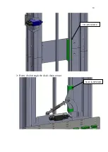
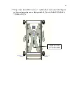
Route chain through idler sprocket and attach to car to lifting point, ( brake )
Verify safeties are working properly by lifting sling, allowing chain to go slack, and
confirm the brake are engaged.
Adjust as necessary for smooth operation, brake test at 125% load is required before
commissioning
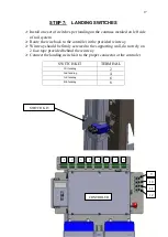
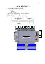
Install floor switches and final limit switch.
Mount floor switches on the LH side of the rail structure.
Run carriage to each floor level and adjust switch


