

8 //
16
Rubex Stair Lift Install Manual | www.Ameriglide.com | 866-378-6648
11819 P/N: 16169 Rev D
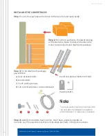
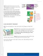
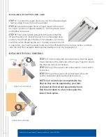
Step 7:
Slide the track and brackets toward the
wall or molding. The edge of the track needs to
be positioned 3
1
/
2
"
from the wall. If there is an
obstruction on the wall; ie: handrail, window sill,
etc; the track will need to be positioned 3
1
/
2
"
out further than the obstruction. Temporarily set
something (like a book) under the bottom of the
track to raise it
1
/
2
"
–
3
/
4
"
off the bottom landing.
This will prevent the track from hitting the floor
later when the track brackets are tightened.
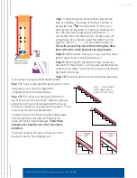
Step 8:
With bracket resting on step, position track
bolt in upper half of track bracket slot.
Step 9:
Starting with the bottom step, screw the
bracket half-way down – remove placed obstruction
used to raise track – and finish by securely attaching
bracket to the step.
Step 10:
Securely tighten remaining track brackets
to the steps using provided wood screws.
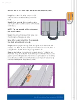
Step 11:
Track is designed to lay directly on the
step noses, or it can be supported
completely by the track brackets.
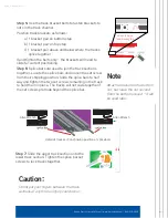
Step 12:
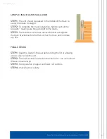
Pull a piece of string taut from the
top of the track to the bottom. Mark any places
where the string is not parallel with the track.
Check the results by using the string again. Track
and string should now be parallel.
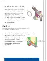
The wall-side of the track may be pulled down
further than the stair side of the track on
steps with thick carpeting/pad.
Final track
adjustment should occur after the unit is
installed.
The track should still move vertically in the
bracket slots for final adjustment.
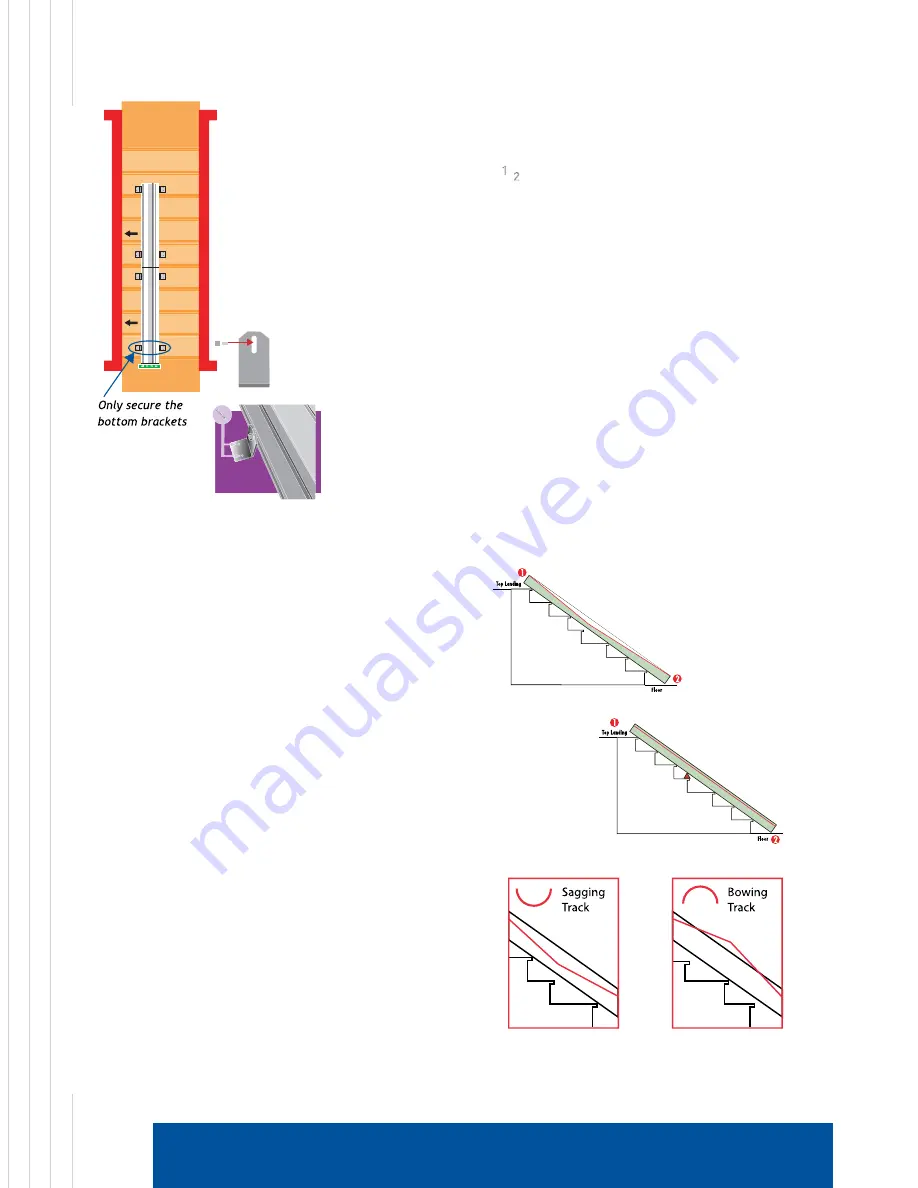
Ilus1. - Track shown
with sagging area
due to “short” step
Summary of Contents for RUBEX
Page 16: ...11819 P N 16169 Rev D ...


