background image

9 // 

16

Rubex Stair Lift Install Manual  |  www.Ameriglide.com  |  866-378-6648

11819    P/N: 16169   Rev D

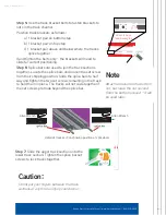
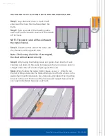
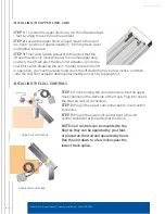
ROUTING THE LOWER CALL CONTROL WIRE

Step 1: On the wall-side of the track, attach call 

control bracket to the second nut up from the 

bottom just above the bottom track bracket.

Step 2:

 Route the wire through the top track 

channel on the wallside of the track.

Step 3:

 At the top of the middle section of track, 

tuck the wire underneath the track out of the way.

Step 4: You will finish routing the call control wire 

after the top track section is in place.
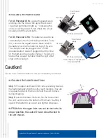
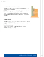
INSTALLING THE UNIT

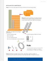
Step 1: Open unit box by cutting down the sides of the box. Fold the sides 

of the box down and slide the unit and top track to the edge of the steps.

Step 2:

 Remove cardboard packing from back of 

footrest.

Step 3:

 Remove the shipping brace from the 

upper section of track and set aside. 

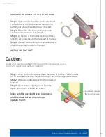
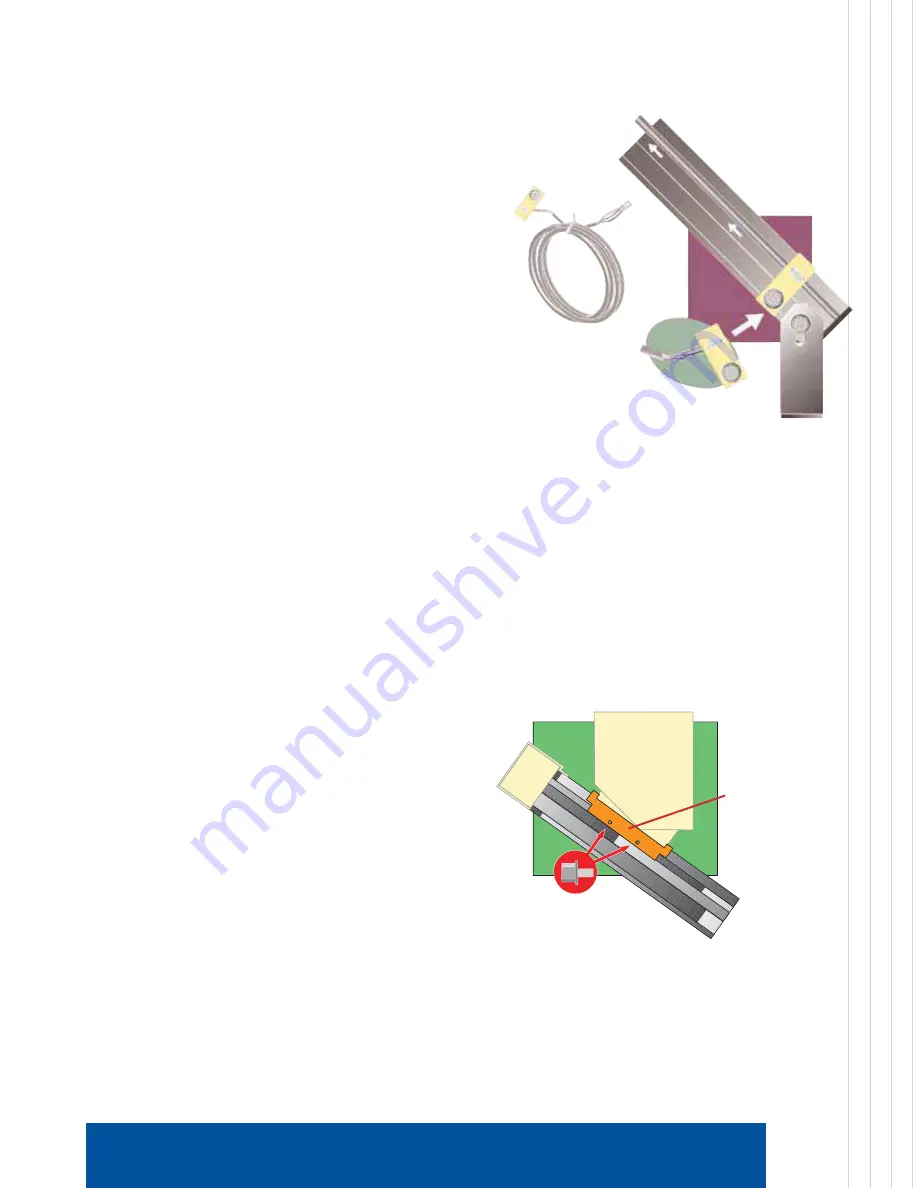
Make sure the packing bracket is removed 
and discarded before attempting to 
operate the lift.

Rave Stair Lift Manual  |  www.Ameriglide.com  |  866-378-6648

Completely remove 

the packing bracket.
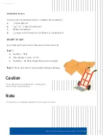
Caution:

Assistance may be needed for this part of the installation due to 

unit’s and upper track section’s weight.

Summary of Contents for RUBEX

Page 1: ...se Any deviation from these instructions will void the LIMITED WARRANTY that accompanies the product Additionally any party installing the product who deviates from the INSTALLATION INSTRUCTIONS shall be taken to agree to INDEMNIFY SAVE AND HOLD HARMLESS the manufacturer from any and all loss liability or damage including attorney fees that might arise out of or in connection with such deviation I...

Page 2: ... sure your installation is safe and successful Please read through them completely prior to attempting to install the unit Indications for Use The Rubex Stair Lift is a transport system also commonly known as a stairway chairlift or stairlift It is a motorized device intended to assist transfers of a single mobility impaired person up or down a flight of stairs Technical Specifications Weight capa...

Page 3: ...Wire______________________ 9 Installing the Unit________________________________________ 9 Slack Cable Reset Procedure___________________________10 Installing Plastic Chain and Traveling Power Cable______11 Installing the Power Cord_______________________________12 Installing the Lower Limit CAM__________________________12 Installing the Seat______________________________________13 Installing the ...

Page 4: ...tep Is there a door or other obstruction at the top that will interfere If so contact your dealer for assistance If after reading the instructions you don t feel capable or comfortable with completing the stair lift installation please contact your dealer for assistance in finding a qualified installer in your area ETL Requirements This ETL listed stair lift must meet the latest ASME A18 1 standar...

Page 5: ...iver d 3 8 socket on 8 Extension in an Electric or Cordless Drill RECEIPT OF UNIT Your stairway lift will arrive in three boxes that consist of Step 1 a Seat Box 38 lb b Unit and top 2 track 115 lb c Track Box 40 80 lb depending on track length Step 2 Check each box for any possible shipping damage Caution Use a dolly or get assistance in carrying the chassis box to avoid injury Note The chassis i...

Page 6: ...ckets and small parts package Step 3 In the small parts package you will find a track brackets bolts b wood screws c 2 self drilling screws d call control extension cord and bracket Step 4 Identify the bottom track section It will have a metal end plate at one end Lay the lower track section on the steps as shown in the picture above Note Top track section will be installed with the unit after ins...

Page 7: ...splice bars and loosen the set screw from their shipping position Slide the spice bars to half way and tighten the two set screws remaining in the track to hold them in place The tracks will not slide together if the set screws protrude beyond the splice bar Note Attach a bracket on the bottom nut but leave the nut second from the bottom unused it will be used later Caution Do not put your fingers...

Page 8: ...tom step screw the bracket half way down remove placed obstruction used to raise track and finish by securely attaching bracket to the step Step 10 Securely tighten remaining track brackets to the steps using provided wood screws Step 11 Track is designed to lay directly on the step noses or it can be supported completely by the track brackets Step 12 Pull a piece of string taut from the top of th...

Page 9: ...routing the call control wire after the top track section is in place INSTALLING THE UNIT Step 1 Open unit box by cutting down the sides of the box Fold the sides of the box down and slide the unit and top track to the edge of the steps Step 2 Remove cardboard packing from back of footrest Step 3 Remove the shipping brace from the upper section of track and set aside Make sure the packing bracket ...

Page 10: ...track section Hand tighten SLACK CABLE RESET PROCEDURE Step 1 During shipping the slack cable device may engage and need to be reset Step 2 With the unit and upper track section installed and power cable unplugged you will use the hand crank to turn the motor belt that turns the cable drum The illustrations show overhead and cut away views of the unit Step 3 Place the manual hand crank onto the mo...

Page 11: ...ble into the channel on the opposite side Note Check every chain link If unsnapped the chain will not bend correctly Step 4 After laying the trailing cable and guide chain into the track channel pull down on the cable to make sure there is no slack and it is straight under the left channel tight against the side Step While holding the cable tight in place use a 1 4 driver to run the self drilling ...

Page 12: ... for the batteries to properly charge The Owners Manual has a page that describes the lights that show on the charger INSTALLING THE LOWER LIMIT CAM Step 1 The upper and lower limit cams are safety devices that automatically stop the unit at each landing They are on opposite sides of the track to hold the unit in place during shipping Step 2 Locate the lower limit cam on the track under the unit a...

Page 13: ...arm to rotate the seat to gain access to all 4 holes STEP 5 If the seat is not level then you will need to adjust the seat leveling STEP 6 There are 4 hex head screws that hold the seat level There are two on the footrest side of the chassis and two on the back side Loosen all four a couple of turns they cannot be taken out STEP 7 Firmly level the seat by pushing up on one arm and down on the othe...

Page 14: ...unit In order to return the lift to operation you must manually hand crank the lift down the track a few inches and then slide the final limit actuator down approximately one inch by tapping on it INSTALLING THE CALL CONTROLS STEP 1 Finish routing the call control wire into the upper track channel on the wall side of the track Plug into one of the two call control connectors STEP 2 Plug in the upp...

Page 15: ...of the brackets making sure they are tight to the stairs STEP 3 Press down on the track at each bracket and tighten the track bracket bolts to further anchor the track and minimize any flex FINAL CHECKS STEP 1 Read the Owner s Manual before riding the lift or allowing anyone else to ride the unit STEP 2 Test unit controls located on the chair arm run unit a short distance down and up STEP 3 Test o...

Page 16: ...11819 P N 16169 Rev D ...

Reviews: