STRATOS VERTICAL PLATFORM LIFTS:
Install Manual
04DEC2020 | 630-00147 REV A
15
INSTALLATION
STRATOS: SECTION 4
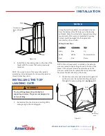
Screw
Curved corner of
ramp roller guide
UP
Screw
Figure 4-6
5. Install the ramp roller guide on the side of the
tower with the screw that were previously
removed.
NOTE: The curved corner of the ramp roller guide is
oriented up. For taller towers the ramp roller guide has
three (3) mounting points.
INSTALLING THE TOP
LANDING GATE
1. Determine the direction and routing of the
wires going to the landing gate.
A length of multi-conductor wire will need to be run
from the bottom of the lift tower up to the landing
call/sends. Consult local codes for type and mounting
requirements. After wiring is completed, the wiring
harness must be plugged into the appropriate
receptacle on the controller.
Wiring Connections:
Call/Send
Lift Harness
Wire
Blue
Blue
Up
White
White
Communication
Red
Red
Down
NOTICE
NOTE: If the call send switch is installed in the gate, the
wires are routed between the gate and to the top of the
tower. If the call send is located outside the gate, the
wires are routed from the gate to the call send box and
then from the box to the top of the tower.
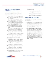
2. Create the necessary space below the gate sill
so the wire can be routed into the gate post
through the wire routing slot. See Figure 4-7.
Post slots
Hole
plugs
Wire routing
slots
Sill
mounting
slots
Figure 4-7
The top of the gate must be attached to a
supporting structure. The gate is not designed to
be freestanding.
WARNING
!


