6
GUIDE RAILS INSTALLATION
(SELF SUPPORTING)
If the adjacent wall is not strong enough to support the reactions stated in the
installation drawing, it is feasible to install self supporting legs on each step.
These legs shall be evenly distributed, the same way as the stud would be
located in a standard wall. The maximum spand between 2 legs is 16’’.
a) Locate the legs on each step, plumb.
b) Use all mounting holes
c) Use only specified anchors on the installation drawing
d) Use ¼-20 UNC screw for rail mounting on the legs.
Anchors legs example
Summary of Contents for Titan Incline Lift
Page 1: ...INSTALLATION Titan Incline Lift ...
Page 8: ...9 UPPER MECHANICAL STOP ...
Page 11: ...12 INSPECTION Titan ...
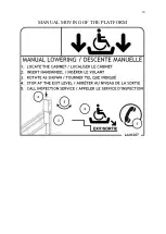
Page 13: ...14 MANUAL MOVING OF THE PLATFORM ...
Page 20: ...21 MAINTENANCE Titan Incline ...
Page 23: ...24 USER MANUAL Titan Incline Lift ...
Page 25: ...26 RATING PLATE ...


