51
098-0010 Rev C
9.2
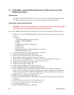
IFU 98-9078A – Updating Mitsubishi FX3G PLC Software with the FX3G-
EEPROM-32L Module
BACKGROUND
The Mitsubishi FX3G-EEPROM-32L module offers a means of updating the Mitsubishi FX3G
PLC software without the need of a PC, programming cabling or special software.
PROCEDURE FOR SOFTWARE UPDATING
WARNING: This procedure requires that the electrical panel door be open while power
is on. Always use caution while working in live electrical panels.
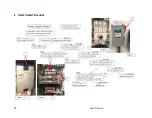
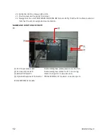
Refer to the ‘NAMES AND FUNCTIONS OF PARTS’ section of this document for pictorial references.
1.
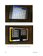
Navigate to the unit’s SOFTWARE VERSIONS HMI screen. Write down current PLC software
version.
•
MediQA:
CALIBRATION MENU (Password Required)
SYSTEM – “SYSTEM VERSION”
•
Heatsan:
CURRENT SETUP (Password Required)
SYSTEM SETUP
FACTORY SETUP
NEXT PAGE (until FACTORY SETUP PAGE 5 is reached)
SOFTWARE VERSIONS – “PLC”
2.
Turn the panel power OFF via the power disconnect switch.
3.
Verify that the PLC Power Status LED is OFF.
4.
Place the PLC RUN/STOP switch in the STOP position.
5.
Remove plastic cover from expansion board on the PLC.
6.
Gently install the FX3G-EEPROM-32L module into the Optional Equipment Connector.
7.
With the electrical panel door open, turn the panel power ON.
8.
Verify that the PLC Power Status LED is ON.
9.
Verify the PLC Run Status LED is OFF.
10.
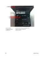
Raise the FX3G-EEPROM-32L module’s front cover.
11.
Press the [WR] key one time. The [WR] LED will illuminate.
12.
Press the [WR] key again. The [WR] LED will blink. Writing is executing. Depending on
program size, the program writing can take several seconds to complete. The [WR] LED will
blink as long as data is written. When the [WR] LED stops blinking the writing is complete.
13.
When writing is complete, turn the panel power OFF.
14.
Verify that the PLC Power Status LED is OFF.
15.
Remove the FX3G-EEPROM-32L module from the expansion board by gently pulling on the
front cover.
16.
Install the plastic cover back on to the expansion board.
17.
Place the PLC RUN/STOP switch in the RUN position.
18.
Turn the panel power ON.
19.
Verify that the PLC Power Status LED is ON.
Summary of Contents for MediQA
Page 2: ......
Page 4: ...2 098 0010 Rev C 1 COMPONENT IDENTIFICATION 1 1 MSP Components ...
Page 5: ...3 098 0010 Rev C ...
Page 6: ...4 098 0010 Rev C ...
Page 7: ...5 098 0010 Rev C 1 2 MDP Components ...
Page 8: ...6 098 0010 Rev C ...
Page 9: ...7 098 0010 Rev C ...
Page 11: ...9 098 0010 Rev C 2 2 Flow Schematics 2 2 1 MSP Schematics ...
Page 12: ...10 098 0010 Rev C ...
Page 13: ...11 098 0010 Rev C ...
Page 14: ...12 098 0010 Rev C ...
Page 15: ...13 098 0010 Rev C ...
Page 16: ...14 098 0010 Rev C ...
Page 17: ...15 098 0010 Rev C ...
Page 18: ...16 098 0010 Rev C ...
Page 19: ...17 098 0010 Rev C ...
Page 20: ...18 098 0010 Rev C ...
Page 21: ...19 098 0010 Rev C ...
Page 22: ...20 098 0010 Rev C ...
Page 23: ...21 098 0010 Rev C ...
Page 24: ...22 098 0010 Rev C ...
Page 25: ...23 098 0010 Rev C 2 2 2 MDP Schematics ...
Page 26: ...24 098 0010 Rev C ...
Page 27: ...25 098 0010 Rev C ...
Page 28: ...26 098 0010 Rev C ...
Page 29: ...27 098 0010 Rev C ...
Page 30: ...28 098 0010 Rev C ...
Page 31: ...29 098 0010 Rev C ...
Page 32: ...30 098 0010 Rev C ...
Page 33: ...31 098 0010 Rev C ...
Page 34: ...32 098 0010 Rev C ...
Page 35: ...33 098 0010 Rev C ...
Page 36: ...34 098 0010 Rev C ...
Page 37: ...35 098 0010 Rev C ...

