26
98-0155 Rev. C
4.3 INITIAL STARTUP
WARNING: This Reverse Osmosis System (RO) contains a preservative solution to
prevent microbiological growth and freezing. Discard all product water for
at least two hours of operation before placing the RO in service.
1. Secure the RO to the floor.
2. Remove the protective covers from the PRODUCT WATER, REJECT WATER TO
DRAIN and INCOMING TAP WATER threaded fittings on the back of the MROZ, and
connect them to the respective threaded fittings in the installation kit.
3. Slide the hose clamps over the hoses that were provided in the installation kit for
holding the 3 hoses in place on the MROZ.
4. Slip the INCOMING TAP WATER, PRODUCT WATER and REJECT WATER TO
DRAIN hoses over the appropriately sized barbed fitting, then secure each with a hose
clamp.
CAUTION:
All hoses MUST be fully inserted over the barbed area and
completely seated over fitting for full clamp engagement.
5. Using the hose supplied for the INCOMING TAP WATER, connect the MROZ
INCOMING TAP WATER hose to the potable blended water supply. If blending both
warm and cold water to improve product flow rate, do not exceed 90° F (33° C).
6. Using the hose supplied for the REJECT WATER TO DRAIN, connect the MROZ
REJECT WATER to a drain location. Leave at least a 2" air gap between the hose and
the drain to prevent contamination or siphoning.
7. Using the hose supplied for the PRODUCT WATER, connect the MROZ PRODUCT
WATER to a drain until the start-up flush and initial disinfection cycle are completed,
and the water quality meets standards below the conductivity set point, and not in
alarm.
8. Open the cabinet door, and ensure that the “CIP” switch on the back of the controller is
in the “OFF” position.
CAUTION:
All the main power wiring for system must be done by a
qualified electrician. None of the 3 phase wiring can be done
by any unauthorized personal.
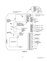
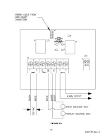
9. Wire main power from a UL Listed, lockable, NEMA 4X rated 3 phase fused disconnect
capable of 240VAC, 30AMP, 31.18kVA (For the 208/230V models) and 600VAC,
30AMP, 31.18kVA (For the 460V models) to connection box inside of MROZ cabinet.
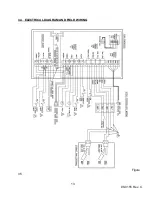
See wiring diagram in section 3.3.
Summary of Contents for MRO3Z
Page 2: ...98 0155 Rev C ...
Page 5: ...98 0155 Rev C ...
Page 13: ...8 98 0155 Rev C MRO7Z and MRO8Z CONFIGURATION SHOWN BELOW Figure 3 2 ...
Page 15: ...10 98 0155 Rev C 3 2 INTERNAL CABINET TOP AND SIDE VIEW Figure 3 3 ...
Page 16: ...11 98 0155 Rev C 3 3 INTERNAL CABINET TOP AND SIDE VIEW CONT Figure 3 4 ...
Page 18: ...13 98 0155 Rev C 3 4 ELECTRICAL DIAGRAM AND FIELD WIRING Figure 3 5 ...
Page 19: ...14 98 0155 Rev C Fig Figure 3 6 ...
Page 20: ...15 98 0155 Rev C Figure 3 7 ...
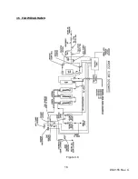
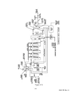
Page 21: ...16 98 0155 Rev C 3 5 FLOW DIAGRAMS Figure 3 8 ...
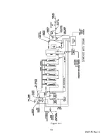
Page 22: ...17 98 0155 Rev C Figure 3 9 ...
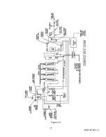
Page 23: ...18 98 0155 Rev C Figure 3 10 ...
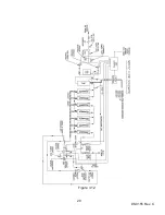
Page 24: ...19 98 0155 Rev C Figure 3 11 ...
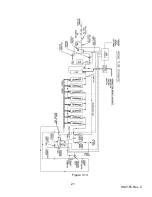
Page 25: ...20 98 0155 Rev C Figure 3 12 ...
Page 26: ...21 98 0155 Rev C Figure 3 13 ...
Page 46: ...41 98 0155 Rev C FIGURE 6 3 ...

