42
98-0155 Rev. C
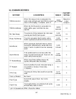
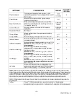
6.4 STANDARD SETPOINTS
SETPOINT
DESCRIPTION
RANGE
FACTORY
SETTING
TDS/Cond Limit
When this value is met or exceeded, the
alarm lamp will light and high TDS/Cond will
show on the display. To disable, set to 0.
0-999
µS or PPM*
Based on
water
analysis.
TDS/Cond Delay
When the limit Set point is exceeded, no
alarm will be given until this time has
expired.
0-999
seconds
10
RO Start Delay
The amount of time between the inlet valve
opening and the RO pump start.
0-99
seconds
10
Press Fault Delay
The time a pressure fault must be active
before a pressure fault shut down occurs.
0-99
seconds
10
Auto Reset
When a pressure fault shut down is active,
the system will attempt to restart after this
delay. If set to 0, system must be manually
reset.
0-99
minutes
0
Alarm Silence
If the audible alarm is silenced, after this
delay, the alarm will resound. If set to 0, the
alarm will remain silenced.
0-99
minutes
3
TF Restart Delay
When a tank full condition clears, the
system will restart after this delay.
0-99
sec/min
3
TF Restart
Selects whether the tank full restart delay is
in seconds or minutes. 0=seconds,
1=minutes.
0-1
0
TFO Time
The amount of time that a tank full override
lasts.
0-15
minutes
3
Tank Lo Restart
Not Used
Flush Type
Selects the type of flush. Set to 0 to
disable.
0-8
0
Flush Time
The length of time a membrane flush cycle
will last when flush is active.
0-99
0
* µS = microsiemens; PPM = Parts Per Million
Summary of Contents for MRO3Z
Page 2: ...98 0155 Rev C ...
Page 5: ...98 0155 Rev C ...
Page 13: ...8 98 0155 Rev C MRO7Z and MRO8Z CONFIGURATION SHOWN BELOW Figure 3 2 ...
Page 15: ...10 98 0155 Rev C 3 2 INTERNAL CABINET TOP AND SIDE VIEW Figure 3 3 ...
Page 16: ...11 98 0155 Rev C 3 3 INTERNAL CABINET TOP AND SIDE VIEW CONT Figure 3 4 ...
Page 18: ...13 98 0155 Rev C 3 4 ELECTRICAL DIAGRAM AND FIELD WIRING Figure 3 5 ...
Page 19: ...14 98 0155 Rev C Fig Figure 3 6 ...
Page 20: ...15 98 0155 Rev C Figure 3 7 ...
Page 21: ...16 98 0155 Rev C 3 5 FLOW DIAGRAMS Figure 3 8 ...
Page 22: ...17 98 0155 Rev C Figure 3 9 ...
Page 23: ...18 98 0155 Rev C Figure 3 10 ...
Page 24: ...19 98 0155 Rev C Figure 3 11 ...
Page 25: ...20 98 0155 Rev C Figure 3 12 ...
Page 26: ...21 98 0155 Rev C Figure 3 13 ...
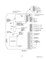
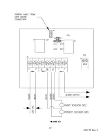
Page 46: ...41 98 0155 Rev C FIGURE 6 3 ...

