
User Guide
6 - 2
Signal Processor
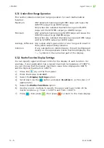
LMG MkII
6.2 Maths Card Electrical Connections
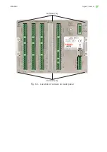
Refer to Fig. 6-1 for the location of the Maths Card connections.
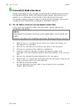
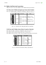
6.2.1 External I/O Maths Analog Output Connection Schedule
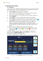
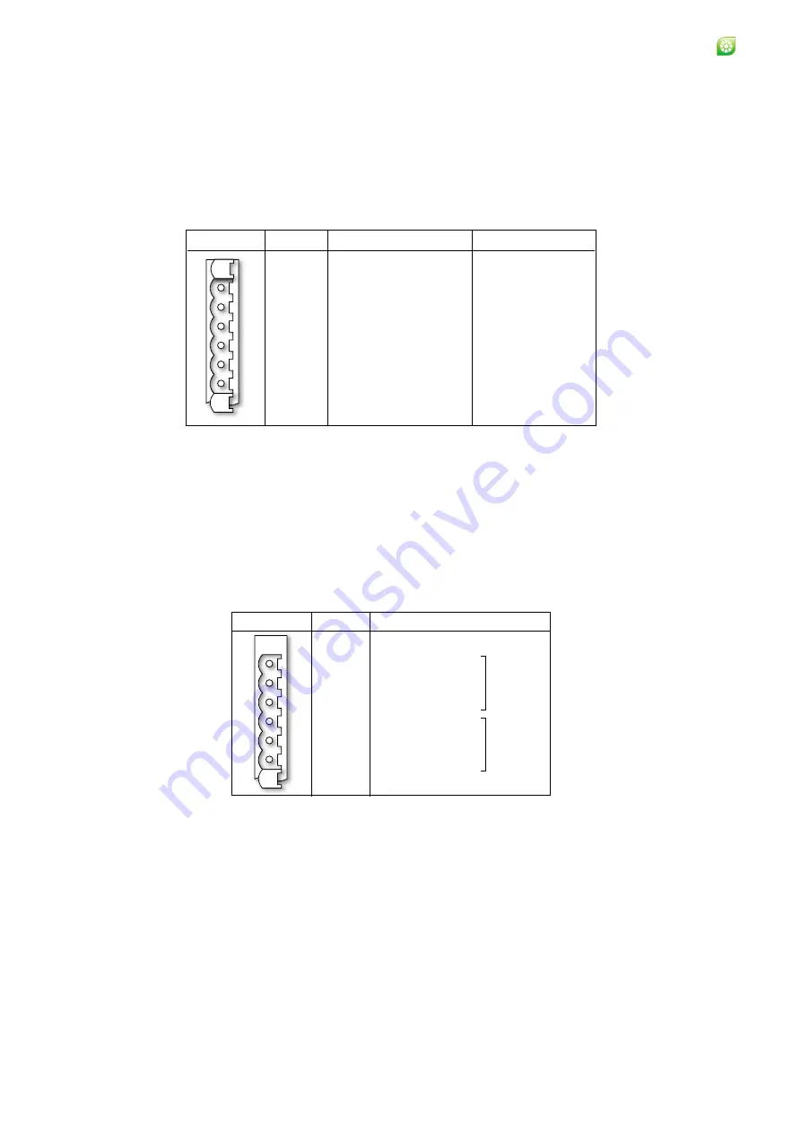
The 4 to 20 mA Output connection schedule is given in Fig. 6-2.
Pin Nº
Function
I +
I -
Screen
V +
V -
Description
Current output drive
Current output return
Screen
Current output drive
Current output return
Maximum loop
resistance: 500
Ω
Load
Minimum load
resistance: 500
Ω
AN
OUT
1
2
3
4
5
6
Screen
Screen
Fig. 6-2 External I/O Analog Output Connections
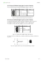
6.2.2 External I/O Maths Alarm Relay Connection Schedule
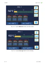
The Alarm Output connection schedule is given in Fig. 6-3.
The alarm relay contact rating is 50 V ac or dc at 0.5 A.
The alarm relays will be in their ‘Alarm’ state when power is removed.
RELAYS
Pin Nº
Function
C
NO
NC
C
NO
NC
Description
Common
Normally Open
Normally Closed
Common
Normally Open
Normally Closed
Alarm 1
Alarm 2
1
2
3
4
5
6
Fig. 6-3 External I/O Alarm Relay Connections
Summary of Contents for LMG MkII
Page 6: ...INTRODUCTION 1 ...
Page 10: ...INSTALLING THE PROCESSOR 2 ...
Page 14: ...User Guide 2 4 Signal Processor LMG MkII Fig 2 4 LMG MkII Electrical System Overview ...
Page 22: ...3 USING THE PROCESSOR ...
Page 44: ...TIME FUNCTION PROCESSING 4 ...
Page 50: ...SERIAL COMMUNICATIONS 5 ...
Page 62: ...Signal Processor LMG MkII Blank ...
Page 63: ...EXTERNAL I O MATHS FUNCTIONS 6 ...
Page 64: ...Signal Processor LMG MkII Screws A Fig 6 1 Location of screws on back panel Screws A ...
Page 88: ...MAINTENANCE 7 ...
Page 92: ...User Guide 7 4 Signal Processor LMG MkII Fig 7 3 USB Export Data option ...