6 - 7
User Guide
LMG MkII
Signal Processor
6.4 Maths Function Options
6.4.1 Maximum
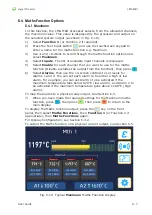
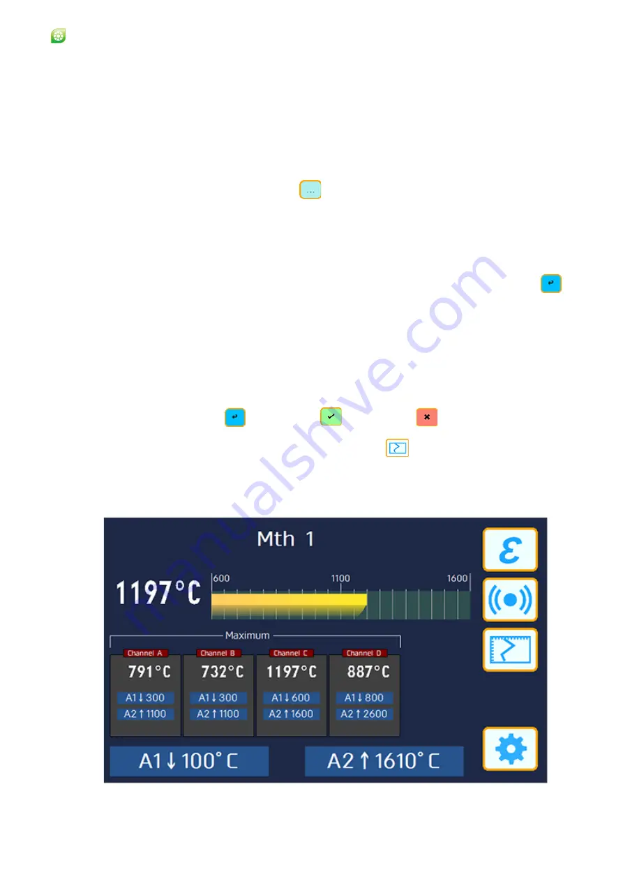
In this function, the LMG MkII processor selects, from the allocated channels,
the maximum value. This value is displayed by the processor and output on
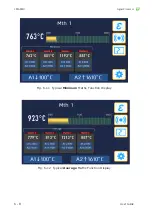
the selected system output (as shown in Fig. 6-10).
1
) Select
Function 1
(or Function 2 if required).
2) Press the Text Input button
and use the touchscreen keypad to
enter a name for the maths function e.g. Maximum.
3) Use
+
and
-
buttons to scroll through the maths function options and
select
Maximum
.
4) Select
Inputs
. The list of available input channels is displayed.
5) Select
Enable
for each channel that you want to use for the maths
function (Disable excludes the output from the function), then press
6) Select
Alarms
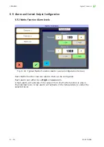
, then use the on-screen controls to set levels for
Alarms 1 and 2. You can set each alarm to be either a high or low
alarm. For example, you can set Alarm 1 to be activated if the
maximum temperature falls below 820 °C (low alarm), and Alarm 2 to
be activated if the maximum temperature goes above 1180 °C (high
alarm).
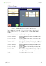
To map the alarms to a physical relay output, See Section 6.5.
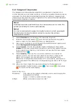
7) When you have made the required settings for the Maximum maths
function, press
, then press
, then press
to return to the
main display.
To display the Maths function output, press the
key on the front
panel, then select
Maths Functions
, then
Function 1
(or Function 2 if
appropriate), then
Maths Functions
again.
For Display Configuration, see Section 6.3.2.
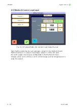
To output the Maths function on a physical current output, see Section 6.5.
Fig. 6-10 Typical
Maximum
Maths Function Display
Summary of Contents for LMG MkII
Page 6: ...INTRODUCTION 1 ...
Page 10: ...INSTALLING THE PROCESSOR 2 ...
Page 14: ...User Guide 2 4 Signal Processor LMG MkII Fig 2 4 LMG MkII Electrical System Overview ...
Page 22: ...3 USING THE PROCESSOR ...
Page 44: ...TIME FUNCTION PROCESSING 4 ...
Page 50: ...SERIAL COMMUNICATIONS 5 ...
Page 62: ...Signal Processor LMG MkII Blank ...
Page 63: ...EXTERNAL I O MATHS FUNCTIONS 6 ...
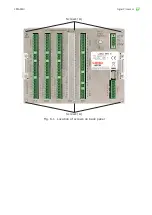
Page 64: ...Signal Processor LMG MkII Screws A Fig 6 1 Location of screws on back panel Screws A ...
Page 88: ...MAINTENANCE 7 ...
Page 92: ...User Guide 7 4 Signal Processor LMG MkII Fig 7 3 USB Export Data option ...


