


6 - 11
User Guide
LMG MkII
Signal Processor
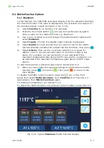
6.4.4 Range
This function displays the range in temperature of the selected channels i.e.
it calculates the absolute difference between the maximum and minimum
temperatures.
This function is set up in a similar way to Maximum (See section 6.4.1),
except that at Step 3, select
Range
.
6.4.5 Difference
In this function, any
TWO
(and only two)
of the four channels can be
allocated. The difference between the two channels is displayed and output
by the processor. The function always subtracts the second of the two
allocated channels from the first (in alphabetical order) and provides a
bipolar output based on the calculation.
e.g.
Selected Channels
Result
A
B
A - B
A
D
A
-
D
C
B
B - C etc.
When operating in difference mode, the analogue output range can be
configured to represent both positive and negative values.
1) Select
Function 1
(or Function 2 if required) (Fig. 6-8).
2) Press the Text Input button
and use the touchscreen keypad to
enter a name for the maths function e.g. Difference.
3) Use
+
and
-
buttons to scroll through the maths function options and
select
Difference
.
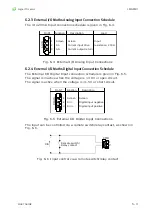
4) Select
Inputs
. The list of available inputs is displayed, then select
Enable
for the two inputs that you want to use for the maths function.
If you select more than two, the function will use the first two inputs
selected. Press
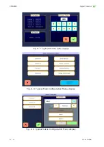
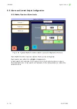
5) Select
Alarms
, then use the on-screen controls to set levels for
Alarms 1 and 2. You can set each alarm to be either a high or low
alarm. For example, you can set Alarm 1 to be activated if the
difference in temperature falls below 10 °C (low alarm), and Alarm 2
to be activated if the difference in temperature goes above 50 °C (high
alarm).
10) When you have made the required settings for the Difference maths
function, press
, then press
, then press
to return to the
main display.
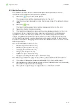
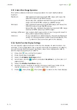
To display the Maths function output, press the
key on the front
panel, then select
Maths Functions
, then
Function 1
(or Function 2 if
appropriate), then
Maths Functions
again.
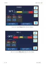
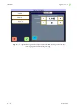
The Difference function will be displayed, similar to Fig. 6-13.
For Display Configuration, see Section 6.3.2.
Summary of Contents for LMG MkII
Page 6: ...INTRODUCTION 1 ...
Page 10: ...INSTALLING THE PROCESSOR 2 ...
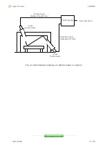
Page 14: ...User Guide 2 4 Signal Processor LMG MkII Fig 2 4 LMG MkII Electrical System Overview ...
Page 22: ...3 USING THE PROCESSOR ...
Page 44: ...TIME FUNCTION PROCESSING 4 ...
Page 50: ...SERIAL COMMUNICATIONS 5 ...
Page 62: ...Signal Processor LMG MkII Blank ...
Page 63: ...EXTERNAL I O MATHS FUNCTIONS 6 ...
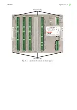
Page 64: ...Signal Processor LMG MkII Screws A Fig 6 1 Location of screws on back panel Screws A ...
Page 88: ...MAINTENANCE 7 ...
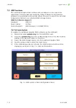
Page 92: ...User Guide 7 4 Signal Processor LMG MkII Fig 7 3 USB Export Data option ...