User Manual
88
i Series / iX Series
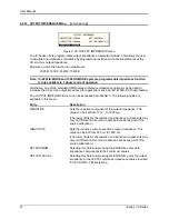
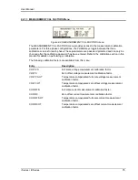
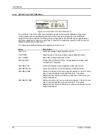
4.6.2.2 Analyzing waveform data
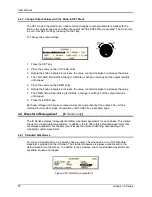
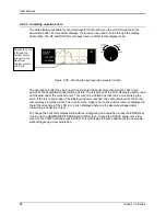
The data displays available for acquired waveform data allow you to scroll through the entire
acquisition buffer. For waveform displays, the knob can be used to scroll through the display
horizontally. The UP and DOWN cursor keys have no effect in this display mode.
Counter
Clock
wise
Clock
wise
INCR
DECR
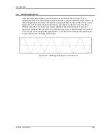
Figure 4-35: Scrolling through acquired waveform data
The acquisition buffer may be longer than the selected horizontal scale in which case only a
portion of the acquisition window will be visible. The left portion of the LCD display is used to read
out the data under the vertical cursor. This cursor is a dotted line that can be moved using the
knob. If the left or right edge of the display window is reached, the entire display will shift so the
cursor always remains visible. The time from the trigger point to the vertical cursor is displayed in
the left hand portion of the LCD in ms. Also displayed here are the absolute voltage and/or
current value under the cursor.
To change the horizontal display scale without re-triggering an acquisition, press the ENTER key
to return to the HARMONICS/TRACE ANALYSIS screen, change the SCALE value, move the
cursor to the VIEW field and press ENTER. This will display the same data set at the new scale
without triggering a new acquisition.
Readouts on the
left track the
vertical cursor
position on the
waveform.
Trigger point is
at 0.0 ms.
Summary of Contents for 10001i
Page 2: ......
Page 3: ......
Page 6: ...ii This page intentionally left blank...
Page 38: ...User Manual 24 i Series iX Series Figure 3 5 Rear Panel View for the 3001i 3001iX...
Page 39: ...User Manual i Series iX Series 25 Figure 3 6 Rear Panel View for the 5001i 5001iX...
Page 43: ...User Manual i Series iX Series 29 Figure 3 8 Functional Test Setup...
Page 44: ...User Manual 30 i Series iX Series Figure 3 9 Single Phase 10000 VA System 10001iX i...
Page 46: ...User Manual 32 i Series iX Series Figure 3 11 Single Phase 15000 VA System 15001iX i...
Page 48: ...User Manual 34 i Series iX Series Figure 3 13 Connection With MODE Option...
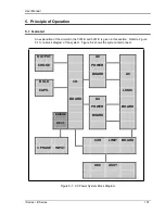
Page 118: ...User Manual 104 i Series iX Series Figure 5 2 Power Source Module Block Diagram...
Page 121: ...User Manual i Series iX Series 107 Figure 5 3 5001i Internal Layout...
Page 122: ...User Manual 108 i Series iX Series Figure 5 4 Logic Board LED s...
Page 124: ...User Manual 110 i Series iX Series Figure 5 5 AC Power Stage Layout...
Page 125: ...User Manual i Series iX Series 111 Figure 5 6 AC Control Logic Block Diagram...
Page 138: ...User Manual 124 i Series iX Series Figure 6 3 Adjustment Location...
Page 152: ...User Manual 138 i Series iX Series Figure 9 4 Voltage Modulation...
Page 219: ...User Manual i Series iX Series 205 Figure 9 36 Example Connection With 5001iX and EOS 1...
Page 221: ...User Manual i Series iX Series 207 Figure 9 38 15003iX CTS EOS3 LR3...
Page 222: ...User Manual 208 i Series iX Series Figure 9 39 15003iX 3 EOS3...
Page 233: ...User Manual i Series iX Series 219 Figure 9 41 Example Connection With MODE iX...
Page 240: ...User Manual 226 i Series iX Series Figure 9 42 Example Connections With OMNI 1 18i...
Page 241: ...User Manual i Series iX Series 227 Figure 9 43 Example Connections With OMNI 3 18i...

