User Manual
96
i Series / iX Series
4.7.5 List Transients
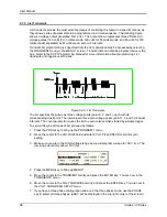
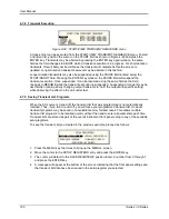
List transients provide the most versatile means of controlling the output in a specific manner as
they allow a series of parameters to be programmed in a timed sequence. The following figure
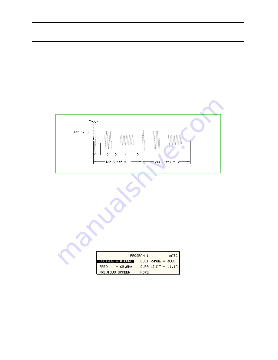
shows a voltage output generated from a list. The output shown represents three different AC
voltage pulses (160 volts for 33 milliseconds, 120 volts for 83 milliseconds, and 80 volts for 150
milliseconds) separated by 67 millisecond, zero volt intervals.
Transient list programming is supported from the front panel and may be accessed by selecting
the TRANSIENTS entry in the MENU 1 screen. Transient lists can also be programmed over the
bus. Refer to the SCPI Programming Manual for more information about programming List
transients and triggers over the bus.
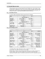
Figure 4-40: List Transients
The list specifies the pulses as three voltage points (point 0, 2, and 4), each with its
corresponding dwell point. The intervals are three zero-voltage points (point 1, 3, and 5) of equal
intervals. The count parameter causes the list to execute twice when started by a single trigger.
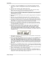
To set up this type of transient list, proceed as follows:
1. Press the PROG key to bring up the PROGRAM 1 menu.
2. Move the cursor to the VOLTAGE field and enter 0 Volt. Press ENTER to confirm your
setting.
3. Make sure you are in the HIGH voltage range as we will program a surge to 160 V rms. The
low range would only allow 150 V rms.
4. Press the MENU key to bring up MENU 1.
5. Move the cursor to the TRANSIENTS entry and press the ENTER key. You are now in the
TRANSIENTS menu.
6. Move the cursor to the VOLT SURGE/SAG entry and press the ENTER key. You are now in
the VOLT SURGE/SAG SETUP menu.
7. If you have a three phase configuration and are in the three phase mode, use the PHASE
key to select all three phases. (øABC will be displayed in the top right corner of the screen.)
Summary of Contents for 10001i
Page 2: ......
Page 3: ......
Page 6: ...ii This page intentionally left blank...
Page 38: ...User Manual 24 i Series iX Series Figure 3 5 Rear Panel View for the 3001i 3001iX...
Page 39: ...User Manual i Series iX Series 25 Figure 3 6 Rear Panel View for the 5001i 5001iX...
Page 43: ...User Manual i Series iX Series 29 Figure 3 8 Functional Test Setup...
Page 44: ...User Manual 30 i Series iX Series Figure 3 9 Single Phase 10000 VA System 10001iX i...
Page 46: ...User Manual 32 i Series iX Series Figure 3 11 Single Phase 15000 VA System 15001iX i...
Page 48: ...User Manual 34 i Series iX Series Figure 3 13 Connection With MODE Option...
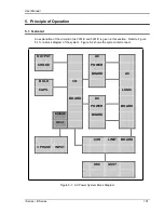
Page 118: ...User Manual 104 i Series iX Series Figure 5 2 Power Source Module Block Diagram...
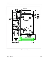
Page 121: ...User Manual i Series iX Series 107 Figure 5 3 5001i Internal Layout...
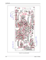
Page 122: ...User Manual 108 i Series iX Series Figure 5 4 Logic Board LED s...
Page 124: ...User Manual 110 i Series iX Series Figure 5 5 AC Power Stage Layout...
Page 125: ...User Manual i Series iX Series 111 Figure 5 6 AC Control Logic Block Diagram...
Page 138: ...User Manual 124 i Series iX Series Figure 6 3 Adjustment Location...
Page 152: ...User Manual 138 i Series iX Series Figure 9 4 Voltage Modulation...
Page 219: ...User Manual i Series iX Series 205 Figure 9 36 Example Connection With 5001iX and EOS 1...
Page 221: ...User Manual i Series iX Series 207 Figure 9 38 15003iX CTS EOS3 LR3...
Page 222: ...User Manual 208 i Series iX Series Figure 9 39 15003iX 3 EOS3...
Page 233: ...User Manual i Series iX Series 219 Figure 9 41 Example Connection With MODE iX...
Page 240: ...User Manual 226 i Series iX Series Figure 9 42 Example Connections With OMNI 1 18i...
Page 241: ...User Manual i Series iX Series 227 Figure 9 43 Example Connections With OMNI 3 18i...


