User Manual
98
i Series / iX Series
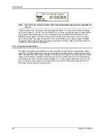
Note: The AC source output remains at the last programmed values at the completion of
the list.
In three phase mode, the voltage lists are phase selectable. You can set up a different voltage
list for each phase. To do this, use the PHASE key to choose the desired phase, as described in
the example. Note that fields common to all phases such as DURATION, END DELAY and
REPEAT always apply to all three phases in three phase mode. When the cursor is moved to
any of these fields, the phase annunciator in the top right-hand corner always reverts to øABC.
Frequency transients are identical to voltage transients except they apply to all three phases at
all times in a three phase configuration.
4.7.6 Programming Slew Rates
As shown in the previous examples there are a number of ways that you can generate custom
waveforms. Programmable slew rates provide additional flexibility when customizing waveforms.
Slew rates determine how fast the voltage or frequency is changed by the controller when a step,
pulse, or list transient is triggered. Slew rates cannot be programmed from the front panel and
are always set to their maximum values at power on. To use programmable slew rates, the AC
source must be programmed over the bus. Refer to the SCPI Programming Manual for more
information about programming slew rates.
Summary of Contents for 10001i
Page 2: ......
Page 3: ......
Page 6: ...ii This page intentionally left blank...
Page 38: ...User Manual 24 i Series iX Series Figure 3 5 Rear Panel View for the 3001i 3001iX...
Page 39: ...User Manual i Series iX Series 25 Figure 3 6 Rear Panel View for the 5001i 5001iX...
Page 43: ...User Manual i Series iX Series 29 Figure 3 8 Functional Test Setup...
Page 44: ...User Manual 30 i Series iX Series Figure 3 9 Single Phase 10000 VA System 10001iX i...
Page 46: ...User Manual 32 i Series iX Series Figure 3 11 Single Phase 15000 VA System 15001iX i...
Page 48: ...User Manual 34 i Series iX Series Figure 3 13 Connection With MODE Option...
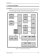
Page 118: ...User Manual 104 i Series iX Series Figure 5 2 Power Source Module Block Diagram...
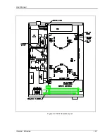
Page 121: ...User Manual i Series iX Series 107 Figure 5 3 5001i Internal Layout...
Page 122: ...User Manual 108 i Series iX Series Figure 5 4 Logic Board LED s...
Page 124: ...User Manual 110 i Series iX Series Figure 5 5 AC Power Stage Layout...
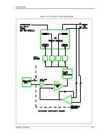
Page 125: ...User Manual i Series iX Series 111 Figure 5 6 AC Control Logic Block Diagram...
Page 138: ...User Manual 124 i Series iX Series Figure 6 3 Adjustment Location...
Page 152: ...User Manual 138 i Series iX Series Figure 9 4 Voltage Modulation...
Page 219: ...User Manual i Series iX Series 205 Figure 9 36 Example Connection With 5001iX and EOS 1...
Page 221: ...User Manual i Series iX Series 207 Figure 9 38 15003iX CTS EOS3 LR3...
Page 222: ...User Manual 208 i Series iX Series Figure 9 39 15003iX 3 EOS3...
Page 233: ...User Manual i Series iX Series 219 Figure 9 41 Example Connection With MODE iX...
Page 240: ...User Manual 226 i Series iX Series Figure 9 42 Example Connections With OMNI 1 18i...
Page 241: ...User Manual i Series iX Series 227 Figure 9 43 Example Connections With OMNI 3 18i...

