User Manual
106
i Series / iX Series
5.6 DC-DC Power Converter
The DC-DC power converter, A3, is powered from the rectified AC input. The converter is a
PWM (pulse width modula
ted) full bridge type that uses IGBT‟s as the power switches. The
control logic supply for the DC-DC converter is derived from the auxiliary power supply so the
DC-DC converter does not start switching until after the auxiliary power supply has started up
and comes into regulation. This feature ensures a smooth start up.
The output of the DC converter is automatically selected for 250 VDC or 500 VDC output
depending on whether the low range output (135/150 Vac) or high range output (270/300 Vac) is
selected. The 250/500 VDC range selection is made by a relay that selects one of two taps on
the DC output transformer. The converter is fully protected with input current limit and
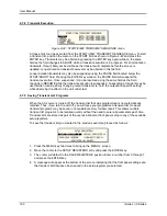
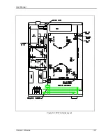
overvoltage protection. When the output of the DC converter is up and in regulation, the LED on
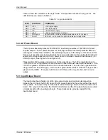
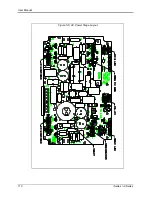
the input/output board will be lit. The LED can only be seen by looking directly down between the
large storage capacitors and the input/output board. (See Figure 5-3)
5.7 AC Control Logic
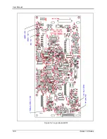
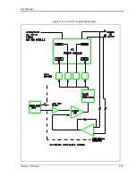
The main function of the control board, A4, is to generate the gate drive signals for the AC power
stage. This board also includes the circuit for the current limit and when two or three units are
operated in parallel, the load sharing circuit. (See Figure 5-6)
The signal from the oscillator is fed through a low pass filter circuit and sent to the reference
input of the error amplifier. The voltage output of the unit is differentially sensed and fed back to
the error amplifier thereby completing the control loop. The output of the error amplifier drives a
37.5 kHz pulse width modulator. The modulator output is sent to four gate drivers which drive
the IGBT‟s on the AC power board after going through opto couplers that provide the necessary
isolation.
Summary of Contents for 10001i
Page 2: ......
Page 3: ......
Page 6: ...ii This page intentionally left blank...
Page 38: ...User Manual 24 i Series iX Series Figure 3 5 Rear Panel View for the 3001i 3001iX...
Page 39: ...User Manual i Series iX Series 25 Figure 3 6 Rear Panel View for the 5001i 5001iX...
Page 43: ...User Manual i Series iX Series 29 Figure 3 8 Functional Test Setup...
Page 44: ...User Manual 30 i Series iX Series Figure 3 9 Single Phase 10000 VA System 10001iX i...
Page 46: ...User Manual 32 i Series iX Series Figure 3 11 Single Phase 15000 VA System 15001iX i...
Page 48: ...User Manual 34 i Series iX Series Figure 3 13 Connection With MODE Option...
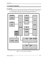
Page 118: ...User Manual 104 i Series iX Series Figure 5 2 Power Source Module Block Diagram...
Page 121: ...User Manual i Series iX Series 107 Figure 5 3 5001i Internal Layout...
Page 122: ...User Manual 108 i Series iX Series Figure 5 4 Logic Board LED s...
Page 124: ...User Manual 110 i Series iX Series Figure 5 5 AC Power Stage Layout...
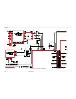
Page 125: ...User Manual i Series iX Series 111 Figure 5 6 AC Control Logic Block Diagram...
Page 138: ...User Manual 124 i Series iX Series Figure 6 3 Adjustment Location...
Page 152: ...User Manual 138 i Series iX Series Figure 9 4 Voltage Modulation...
Page 219: ...User Manual i Series iX Series 205 Figure 9 36 Example Connection With 5001iX and EOS 1...
Page 221: ...User Manual i Series iX Series 207 Figure 9 38 15003iX CTS EOS3 LR3...
Page 222: ...User Manual 208 i Series iX Series Figure 9 39 15003iX 3 EOS3...
Page 233: ...User Manual i Series iX Series 219 Figure 9 41 Example Connection With MODE iX...
Page 240: ...User Manual 226 i Series iX Series Figure 9 42 Example Connections With OMNI 1 18i...
Page 241: ...User Manual i Series iX Series 227 Figure 9 43 Example Connections With OMNI 3 18i...

