
User Manual
i Series / iX Series
131
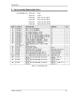
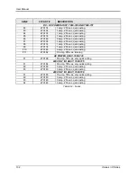
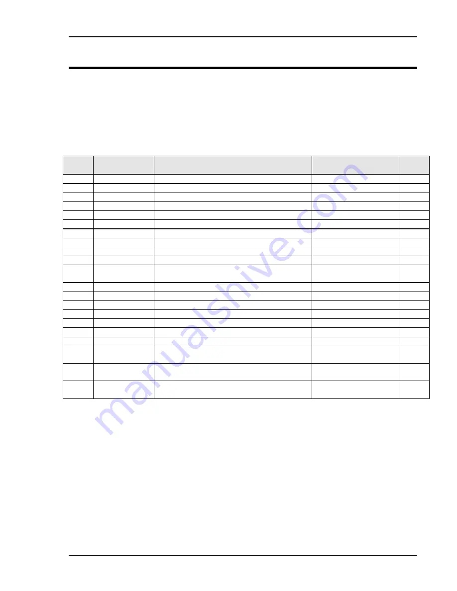
8. Top Assembly Replaceable Parts
TOP ASSEMBLY No: 7000-439-4
3001i
7000-439-1
3001iX
7000-438-3
5001i, 240 VAC INPUT
7000-438-4
5001i, 480 VAC INPUT
7000-438-1
5001iX, 240 VAC INPUT
7000-438-2
5001iX, 480 VAC INPUT
SEQ#
CI PART #
DESCRIPTION
VENDOR
QTY
A1
7000-725-1
240V - I/O PC ASSEMBLY
CI
1
A1
7000-726-1
480V - I/O PC ASSEMBLY
CI
1
A2
7000-419-1
AC POWER MODULE, 3001iX
CI
1
A2
7000-419-2
AC POWER MODULE, 5001iX
CI
1
A3
7000-420-1
240V - DC - DC POWER MODULE, 5001i/iX
CI
1
A3
7000-420-2
240V - DC - DC POWER MODULE, 3001i/iX
CI
1
A3
7000-421-1
480V - DC - DC POWER MODULE
CI
1
A4
7000-732-1
LOGIC BOARD PC ASSEMBLY , 3001iX
CI
1
A4
7000-732-2
LOGIC BOARD PC ASSEMBLY , 5001iX
CI
1
A6
7000-724-1
CURRENT LIMIT PC ASSEMBLY
CI
1
2
7000 43
8-11 THRU -30
PROGRAMMABLE OSC. FRONT PANEL
ASSY.
CI
1
A10
7000-727-1
IEEE 488 BOARD
CI
1
B1
241183
FAN 6 INCH--JD24B2
Rotron
1
F1
270199
FUSE 50A, 700V, AC BOARD
Bussman FWP-50A14F
1
F1
270184
FUSE 30A 700V I/O BOARD
Bussman-KPB30
1
K1
245217
RELAY ON CHASSIS. KUHP-5DT1-24
Potter & Brumfield
1
F
MISC
270183
P.C. FUSES ON DC-DC BD, 3A F
6
,F
10
Bussman PCC-3
3
F
MISC
270174
P.C. FUSES ON DC-DC BD, 1A F
2
-F
5,
F
7
-F
9
Bussman PCC-1
6
CB1
270186
INPUT CIRCUIT BREAKER 35A (240V),
5001i/iX
AIRPAX 205-1111-
28051-2
1
CB1
270196
INPUT CIRCUIT BREAKER 35A (250V),
3001i/iX
AIRPAX IELK21-
28851-1-V
1
CB1
270207
INPUT CIRCUIT BREAKER 15A (480V),
5001i/iX
AIRPAX IELHK-1111-
30431-1-V
1
Table 8-1: Replaceable Parts
Summary of Contents for 10001i
Page 2: ......
Page 3: ......
Page 6: ...ii This page intentionally left blank...
Page 38: ...User Manual 24 i Series iX Series Figure 3 5 Rear Panel View for the 3001i 3001iX...
Page 39: ...User Manual i Series iX Series 25 Figure 3 6 Rear Panel View for the 5001i 5001iX...
Page 43: ...User Manual i Series iX Series 29 Figure 3 8 Functional Test Setup...
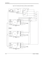
Page 44: ...User Manual 30 i Series iX Series Figure 3 9 Single Phase 10000 VA System 10001iX i...
Page 46: ...User Manual 32 i Series iX Series Figure 3 11 Single Phase 15000 VA System 15001iX i...
Page 48: ...User Manual 34 i Series iX Series Figure 3 13 Connection With MODE Option...
Page 118: ...User Manual 104 i Series iX Series Figure 5 2 Power Source Module Block Diagram...
Page 121: ...User Manual i Series iX Series 107 Figure 5 3 5001i Internal Layout...
Page 122: ...User Manual 108 i Series iX Series Figure 5 4 Logic Board LED s...
Page 124: ...User Manual 110 i Series iX Series Figure 5 5 AC Power Stage Layout...
Page 125: ...User Manual i Series iX Series 111 Figure 5 6 AC Control Logic Block Diagram...
Page 138: ...User Manual 124 i Series iX Series Figure 6 3 Adjustment Location...
Page 152: ...User Manual 138 i Series iX Series Figure 9 4 Voltage Modulation...
Page 219: ...User Manual i Series iX Series 205 Figure 9 36 Example Connection With 5001iX and EOS 1...
Page 221: ...User Manual i Series iX Series 207 Figure 9 38 15003iX CTS EOS3 LR3...
Page 222: ...User Manual 208 i Series iX Series Figure 9 39 15003iX 3 EOS3...
Page 233: ...User Manual i Series iX Series 219 Figure 9 41 Example Connection With MODE iX...
Page 240: ...User Manual 226 i Series iX Series Figure 9 42 Example Connections With OMNI 1 18i...
Page 241: ...User Manual i Series iX Series 227 Figure 9 43 Example Connections With OMNI 3 18i...