User Manual
i Series / iX Series
209
9.4.6 Operation
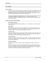
9.4.6.1 General
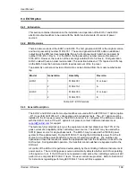
The EOS-1 is used with a California Instruments i/iX power source to perform testing compliant
with the requirements of IEC1000-4-11. The EOS routes the voltage from the power source to
an internal, tapped power transformer. Voltage from each of four taps is sent through an
electronic switch to the EOS-1 output. During IEC1000-4-11 testing, the controlling California
Instruments power source selects which voltage tap to connect to the EOS output. When
IEC1000-4-11 testing is not active, the controlling power source puts the EOS-1 into bypass
mode, shunting the EOS input terminals directly to the output terminals.
All control of the EOS-1 is performed automatically by the California Instruments power source.
The control signals are sent from the power source to the EOS via the option interface cable.
Refer to Section 9.2 for instructions regarding performing IEC1000-4-11 tests with this
equipment.
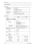
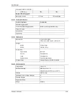
The rated operating current for the EOS in active mode is 18.5 amps. If the controlling power
source is set for an RMS current limit greater than 18.5 amps, it will not activate the EOS unit.
An attempt to do so will indicate Error -
222, “Data out of range”. IEC 1000-4-11 tests may still be
run, but in pre-compliance mode with the EOS unit bypassed.
Note that while the EOS is engaged, there is no Function Strobe output. Normally, the function
strobe - outside the transient system - is associated with any output voltage change. When the
EOS is in use however, the function strobe is generated only when the EOS is engaged. This is
because the output is programmed down during relay activation. These strobes are meaningless
and are not related to any output drops occurring through the EOS. During the EOS transients
that use any of the available EOS drop levels, there are no function strobes. Voltage drops that
do not use one of the available fixed drop levels are done by dropping the output of the power
source itself and will result in functions strobes on J22. It is possible to use the OPTION OUT on
the back of the EOS - a DB9 connector, pin 6. The return can be either pine 2, 3 or 4. The
strobe is a low going level that last for only 400 to 500 nsec. This strobe will coincide with drops
performed by the EOS switch.
If the EOS is already in active mode, the controlling power source will not allow its RMS current
limit to be programmed above 18.5 amps.
The EOS-3 is similar to EOS-1 with provision for three-phase operation.
Summary of Contents for 10001i
Page 2: ......
Page 3: ......
Page 6: ...ii This page intentionally left blank...
Page 38: ...User Manual 24 i Series iX Series Figure 3 5 Rear Panel View for the 3001i 3001iX...
Page 39: ...User Manual i Series iX Series 25 Figure 3 6 Rear Panel View for the 5001i 5001iX...
Page 43: ...User Manual i Series iX Series 29 Figure 3 8 Functional Test Setup...
Page 44: ...User Manual 30 i Series iX Series Figure 3 9 Single Phase 10000 VA System 10001iX i...
Page 46: ...User Manual 32 i Series iX Series Figure 3 11 Single Phase 15000 VA System 15001iX i...
Page 48: ...User Manual 34 i Series iX Series Figure 3 13 Connection With MODE Option...
Page 118: ...User Manual 104 i Series iX Series Figure 5 2 Power Source Module Block Diagram...
Page 121: ...User Manual i Series iX Series 107 Figure 5 3 5001i Internal Layout...
Page 122: ...User Manual 108 i Series iX Series Figure 5 4 Logic Board LED s...
Page 124: ...User Manual 110 i Series iX Series Figure 5 5 AC Power Stage Layout...
Page 125: ...User Manual i Series iX Series 111 Figure 5 6 AC Control Logic Block Diagram...
Page 138: ...User Manual 124 i Series iX Series Figure 6 3 Adjustment Location...
Page 152: ...User Manual 138 i Series iX Series Figure 9 4 Voltage Modulation...
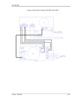
Page 219: ...User Manual i Series iX Series 205 Figure 9 36 Example Connection With 5001iX and EOS 1...
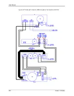
Page 221: ...User Manual i Series iX Series 207 Figure 9 38 15003iX CTS EOS3 LR3...
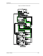
Page 222: ...User Manual 208 i Series iX Series Figure 9 39 15003iX 3 EOS3...
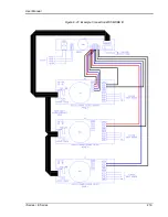
Page 233: ...User Manual i Series iX Series 219 Figure 9 41 Example Connection With MODE iX...
Page 240: ...User Manual 226 i Series iX Series Figure 9 42 Example Connections With OMNI 1 18i...
Page 241: ...User Manual i Series iX Series 227 Figure 9 43 Example Connections With OMNI 3 18i...

