User Manual
306
i Series / iX Series
Control / Display
Description
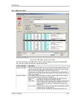
single trigger input. Subsequent repeats will trigger
automatically.
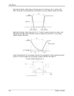
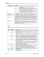
Freq F1 < ta
Sets the frequency before the transient (ta) for Table 2 type
transients. Normally this value is set automatically per Appendix
A, but the operator can change it in this field.
Freq F2 > tb
Sets the frequency after the transient (tb) for Table 2 type
transients. Normally this value is set automatically per Appendix
A, but the operator can change it in this field.
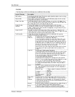
Transient
permutations data
entry grid. (Table)
This data grid displays the T1, T2 and T3 values used for each permutation of
the table values from Appendix A. These values are normally loaded
automatically when selecting a table number using the Type No. drop down list.
It is possible however to edit these values and save them to disk. User defined
transients can be recalled using the File, Open menu. See Menu help below.
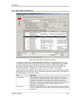
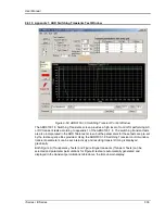
Graph
The graph shows each transient type on a time scale from
–20 msec to 350
msec. Note that for AC mode, only the envelope of the AC waveform is shown
for clarity. Thus, the type of display is the same for AC and DC modes. The
graph can be zoomed using the left mouse button. Double click on the graph to
unzoom.
User Data
The area at the bottom of this tab may be used to enter general information
regarding the unit under test, the test location, operator, and environmental
conditions in effect during the test. This information will be incorporated in the
test reports generated by the GUI.
Menus
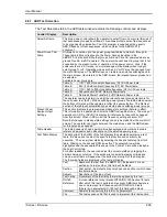
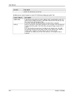
The top of the ABD Transients window contains a standard Windows menu bar. Available menus
are:
Menu
Sub Menu
Description
File
New
The selected resets all data from the Transient permutations data entry grid to
the selected Type No entry. This operation may be used to undo any edits
made by the user.
Open
Opens a specific transient test file with ABD0100_1_8 extension. This menu
may be used to directly select a test file without using the Type No. drop down
list.
Save
Saves the contents of the Transient permutations data entry grid to the
selected test file. The ABD0100_1_8 file extension is automatically appended.
Save As…
Saves the contents of the Transient permutations data entry grid to a user
defined file name. A file dialog box will appear enabling selection of the
directory and file name under which to store the contents of the test sequence
data grid. The ABD0100_1_8 file extension is automatically appended.
Prints a test report using MS Word format. Only data for the presently selected
test sequence is printed.
Note: To print reports, the MS Word report format selection must be made
from the Main GUI, Options menu
Report Format menu before opening the
ABD0100.1.8 test screen. If not, an error prompt will indicate that no
supported report format is selected.
Exit
Closes the ABD Transients test window.
Edit
Cut
Cuts the selected row from the Transient permutations data entry grid. The
data in the row cut is available for a Paste operation.
Copy
Copies the selected row from the Transient permutations data entry grid.
Copied rows can be pasted to the same grid at a different location.
Paste
Pastes a copied row from to the Transient permutations data entry grid.
Run
All
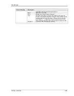
Run selected test
Stop
Abort test in progress
Help
Opens this help file.
Summary of Contents for 10001i
Page 2: ......
Page 3: ......
Page 6: ...ii This page intentionally left blank...
Page 38: ...User Manual 24 i Series iX Series Figure 3 5 Rear Panel View for the 3001i 3001iX...
Page 39: ...User Manual i Series iX Series 25 Figure 3 6 Rear Panel View for the 5001i 5001iX...
Page 43: ...User Manual i Series iX Series 29 Figure 3 8 Functional Test Setup...
Page 44: ...User Manual 30 i Series iX Series Figure 3 9 Single Phase 10000 VA System 10001iX i...
Page 46: ...User Manual 32 i Series iX Series Figure 3 11 Single Phase 15000 VA System 15001iX i...
Page 48: ...User Manual 34 i Series iX Series Figure 3 13 Connection With MODE Option...
Page 118: ...User Manual 104 i Series iX Series Figure 5 2 Power Source Module Block Diagram...
Page 121: ...User Manual i Series iX Series 107 Figure 5 3 5001i Internal Layout...
Page 122: ...User Manual 108 i Series iX Series Figure 5 4 Logic Board LED s...
Page 124: ...User Manual 110 i Series iX Series Figure 5 5 AC Power Stage Layout...
Page 125: ...User Manual i Series iX Series 111 Figure 5 6 AC Control Logic Block Diagram...
Page 138: ...User Manual 124 i Series iX Series Figure 6 3 Adjustment Location...
Page 152: ...User Manual 138 i Series iX Series Figure 9 4 Voltage Modulation...
Page 219: ...User Manual i Series iX Series 205 Figure 9 36 Example Connection With 5001iX and EOS 1...
Page 221: ...User Manual i Series iX Series 207 Figure 9 38 15003iX CTS EOS3 LR3...
Page 222: ...User Manual 208 i Series iX Series Figure 9 39 15003iX 3 EOS3...
Page 233: ...User Manual i Series iX Series 219 Figure 9 41 Example Connection With MODE iX...
Page 240: ...User Manual 226 i Series iX Series Figure 9 42 Example Connections With OMNI 1 18i...
Page 241: ...User Manual i Series iX Series 227 Figure 9 43 Example Connections With OMNI 3 18i...

