


User Manual
48
i Series / iX Series
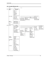
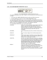
4.2.5 MEASUREMENTS Screens
The i/iX Series uses a DSP based data acquisition system to provide extensive information
regarding the output of the Source. This data acquisition system digitizes the voltage and current
waveforms and calculates several parameters from this digitized data. The result of these
calcalutions is displayed in a series of measurement data screens. The actual digitized
waveforms can also be displayed by selecting the Harmonics/Trace Analysis screen. A total of
four measurement screens are used to display all this information (iX series only).
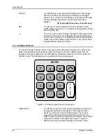
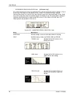
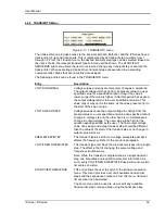
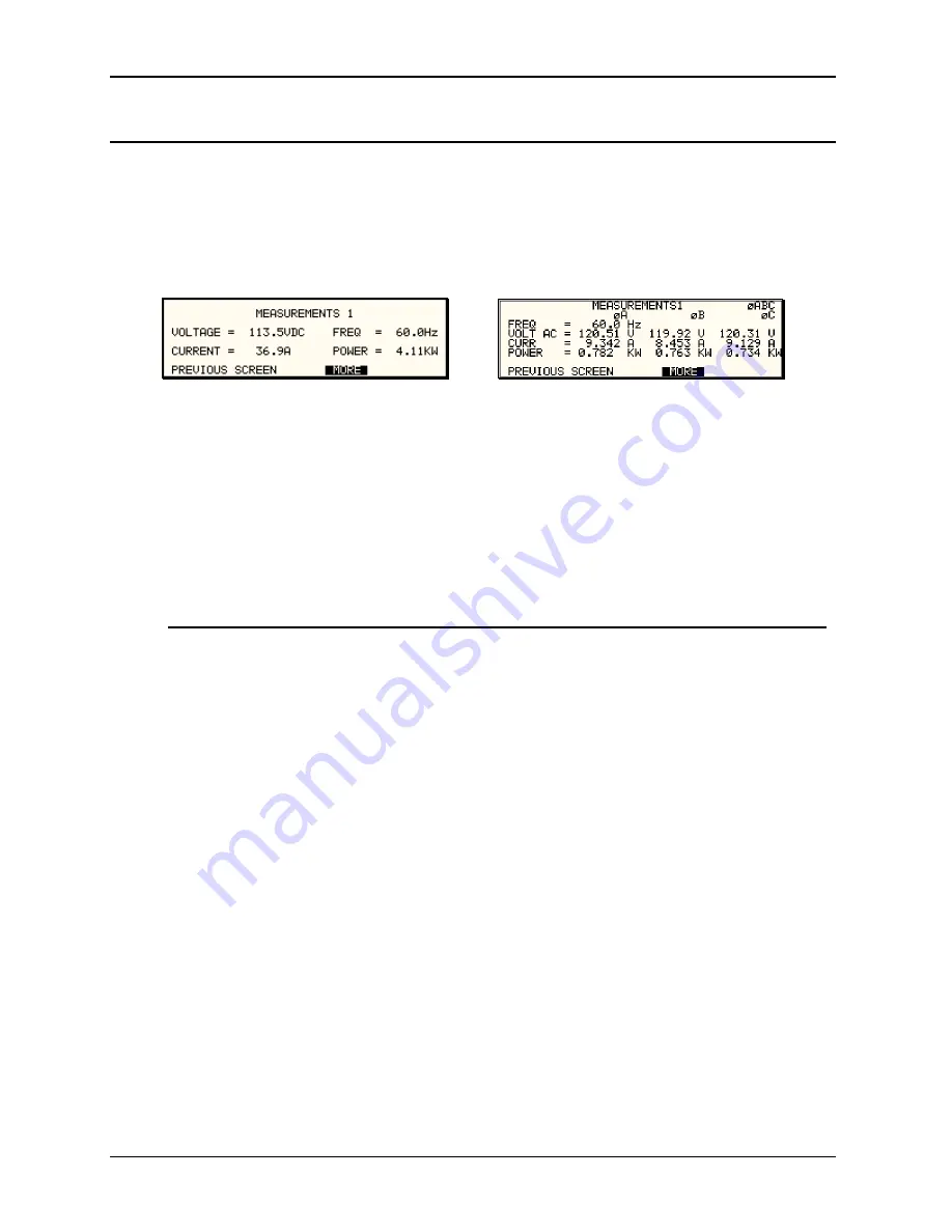
Figure 4-9: MEASUREMENTS Screen, single phase and three phase modes
The first three Measurement screens available on the iX Series are not menus in that no
changes can be made anywhere. Instead, these three screens provide load parameter readouts.
The fourth measurement screen provides access to the advanced measurements and does offer
several user accessible fields (iX Series only). The measurement screens can be reached by
successively pressing the MEAS key which will toggle to all four available screens.
In three phase configuration iX Series, measurements are available for each phase individually.
To select the desired phase, use the PHASE key to toggle through phase A,B,C, or ABC. The
ABC mode displays the data for all three phases simultaneously.
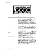
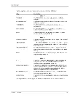
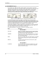
The following parameters are available in the first three measurement screens:
Entry
Description
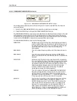
MEASUREMENT 1
VOLTAGE
When in AC or AC+DC mode, this value is the true rms output
voltage measured at the voltage sense lines. In DC only mode,
the voltage is the DC voltage including polarity.
CURRENT
When in AC or AC+DC mode, this value is the true rms output
current drawn by the load. In DC only mode, the current is the
DC current including polarity
FREQ
When in AC or AC+DC mode, the output frequency is measured
at the sense lines. When in DC only mode, this value always
reads “DC”.
POWER
In both AC and DC mode, this value is the real rms. power
consumed by the load.
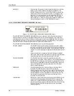
MEASUREMENT 2
VA POWER
In AC or AC+DC mode, this value is the apparent rms. power
consumed by the load. In DC mode, this value is always the
same as the POWER readout.
Summary of Contents for 10001i
Page 2: ......
Page 3: ......
Page 6: ...ii This page intentionally left blank...
Page 38: ...User Manual 24 i Series iX Series Figure 3 5 Rear Panel View for the 3001i 3001iX...
Page 39: ...User Manual i Series iX Series 25 Figure 3 6 Rear Panel View for the 5001i 5001iX...
Page 43: ...User Manual i Series iX Series 29 Figure 3 8 Functional Test Setup...
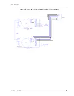
Page 44: ...User Manual 30 i Series iX Series Figure 3 9 Single Phase 10000 VA System 10001iX i...
Page 46: ...User Manual 32 i Series iX Series Figure 3 11 Single Phase 15000 VA System 15001iX i...
Page 48: ...User Manual 34 i Series iX Series Figure 3 13 Connection With MODE Option...
Page 118: ...User Manual 104 i Series iX Series Figure 5 2 Power Source Module Block Diagram...
Page 121: ...User Manual i Series iX Series 107 Figure 5 3 5001i Internal Layout...
Page 122: ...User Manual 108 i Series iX Series Figure 5 4 Logic Board LED s...
Page 124: ...User Manual 110 i Series iX Series Figure 5 5 AC Power Stage Layout...
Page 125: ...User Manual i Series iX Series 111 Figure 5 6 AC Control Logic Block Diagram...
Page 138: ...User Manual 124 i Series iX Series Figure 6 3 Adjustment Location...
Page 152: ...User Manual 138 i Series iX Series Figure 9 4 Voltage Modulation...
Page 219: ...User Manual i Series iX Series 205 Figure 9 36 Example Connection With 5001iX and EOS 1...
Page 221: ...User Manual i Series iX Series 207 Figure 9 38 15003iX CTS EOS3 LR3...
Page 222: ...User Manual 208 i Series iX Series Figure 9 39 15003iX 3 EOS3...
Page 233: ...User Manual i Series iX Series 219 Figure 9 41 Example Connection With MODE iX...
Page 240: ...User Manual 226 i Series iX Series Figure 9 42 Example Connections With OMNI 1 18i...
Page 241: ...User Manual i Series iX Series 227 Figure 9 43 Example Connections With OMNI 3 18i...