User Manual
78
i Series / iX Series
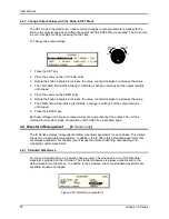
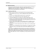
4.3.3 Change Output Values with the Knob in SET Mode
The SET mode of operation is a mode in which changes to output parameters made with the
knob or the entry keypad do not affect the output until the ENTER key is pressed. The AC source
is put in this SET mode by pressing the SET key.
To change the output voltage:
Counter
Clock
wise
Clock
wise
INCR
DECR
1. Press the SET key
2. Place the cursor on the VOLTAGE entry
3. Rotate the knob clockwise to increase the value, counterclockwise to decrease the value
4. The VOLTAGE field will be blinking to indicate a change in settings but the output remains
unchanged.
5. Place the cursor on the FREQ entry
6. Rotate the knob clockwise to increase the value, counterclockwise to decrease the value
7. The FREQ field will be blinking to indicate a change in settings but the output remains
unchanged.
8. Press the ENTER key.
Both new voltage and frequency output values are now present at the output. The unit has
returned to immediate mode of operation until the SET key is pressed again.
4.4 Waveform Management
[
iX Series only
]
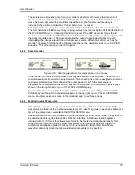
The iX Series employs independent arbitrary waveform generators for each phase. This allows
the user to create custom waveforms. In addition, the iX offers three standard waveforms that
are always available. This chapter covers issues that relate to defining, downloading and
managing custom waveforms.
4.4.1 Standard Waveforms
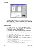
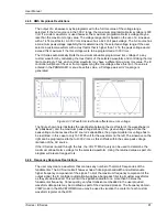
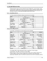
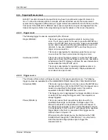
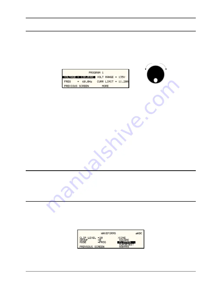
For many AC applications, a sinewave shape is used. The sinewave is one of the standard
waveforms provided on the iX Series. The standard sinewave is always available and is the
default waveform at power-on. In addition to the sinewave, two more standard waveforms are
available, square and clipped.
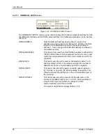
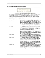
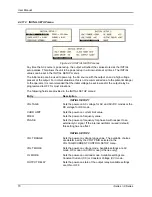
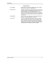
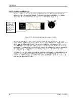
Figure 4-28: Selecting a waveform
Summary of Contents for 10001i
Page 2: ......
Page 3: ......
Page 6: ...ii This page intentionally left blank...
Page 38: ...User Manual 24 i Series iX Series Figure 3 5 Rear Panel View for the 3001i 3001iX...
Page 39: ...User Manual i Series iX Series 25 Figure 3 6 Rear Panel View for the 5001i 5001iX...
Page 43: ...User Manual i Series iX Series 29 Figure 3 8 Functional Test Setup...
Page 44: ...User Manual 30 i Series iX Series Figure 3 9 Single Phase 10000 VA System 10001iX i...
Page 46: ...User Manual 32 i Series iX Series Figure 3 11 Single Phase 15000 VA System 15001iX i...
Page 48: ...User Manual 34 i Series iX Series Figure 3 13 Connection With MODE Option...
Page 118: ...User Manual 104 i Series iX Series Figure 5 2 Power Source Module Block Diagram...
Page 121: ...User Manual i Series iX Series 107 Figure 5 3 5001i Internal Layout...
Page 122: ...User Manual 108 i Series iX Series Figure 5 4 Logic Board LED s...
Page 124: ...User Manual 110 i Series iX Series Figure 5 5 AC Power Stage Layout...
Page 125: ...User Manual i Series iX Series 111 Figure 5 6 AC Control Logic Block Diagram...
Page 138: ...User Manual 124 i Series iX Series Figure 6 3 Adjustment Location...
Page 152: ...User Manual 138 i Series iX Series Figure 9 4 Voltage Modulation...
Page 219: ...User Manual i Series iX Series 205 Figure 9 36 Example Connection With 5001iX and EOS 1...
Page 221: ...User Manual i Series iX Series 207 Figure 9 38 15003iX CTS EOS3 LR3...
Page 222: ...User Manual 208 i Series iX Series Figure 9 39 15003iX 3 EOS3...
Page 233: ...User Manual i Series iX Series 219 Figure 9 41 Example Connection With MODE iX...
Page 240: ...User Manual 226 i Series iX Series Figure 9 42 Example Connections With OMNI 1 18i...
Page 241: ...User Manual i Series iX Series 227 Figure 9 43 Example Connections With OMNI 3 18i...

