


User Manual – Rev J
CS Series
California Instruments
20
chassis configurations, current accuracy specifications are times the number of chassis.
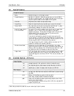
2.1.9 System
Specification
Parameter
Specification
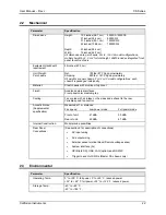
Trigger Input:
External trigger source input. Requires TTL level input signal. Triggers
on negative edge. Response time 80 - 100
μ
s.
Non volatile memory
storage:
16 complete instrument setups and transient lists, 100 events per list.
50 User defined waveforms.
Waveforms
Sine, square, clipped, user defined
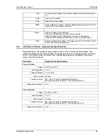
Transients
Parameters:
Current:
Level, Slew rate
Function:
Sine, Clip, Square, User
Frequency: Level, Slew rate
Voltage: Trip
level
Time:
Dwell time, Trigger out
Modes:
Fixed, Pulse, Step, List
Limit Modes:
Two selectable modes of operation:
1. Constant voltage mode (current folds back with automatic recovery)
2. Constant current mode with trip-off (Relays open).
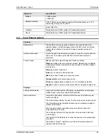
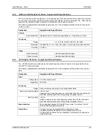
Interfaces
IEEE-488
AH1, DC1, DT1, L3, RL2, SH1, SR1, T6
IEEE 488.2 and SCPI
Response time is 10 ms (typical)
LAN / Ethernet
(-LAN Option)
RJ45 Connector, 10BaseT, 100BaseT or 1000BaseT,
Data transfer rate: 460,800 bps
Protocol: TCP/IP.
Note: If –LAN is installed, RS232C interface is disabled.
RS232C
Baud rates, 9600, 19200, 38400, 57600 and 115200
Data bits: 8, Start bits: 1, Stop bits: 1, Parity: None
Syntax: SCPI
Response time is 10 ms (typical @ 115200 baud)
USB
Standard USB 2.0 peripheral.
Data transfer rate: 460,800 bps
Syntax: SCPI
Note:
Use of the USB port to control more than one power
source from a single PC is not recommended, as communication
may not be reliable. Use GPIB interface for multiple power source
control.
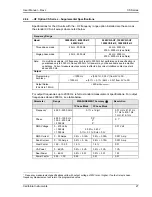
2.1.10 Unit
Protection
Parameter
Specification
Input Over current:
Input Circuit breaker. This breaker protects the equipment only and is not
a branch protection device. AC input connection should be make using a
suitable branch protection device per local electrical code.
Input Over voltage
Transients:
Surge protection to withstand EN50082-1 (IEC 801-4, 5) levels.


