User Manual – Rev J
CS Series
California Instruments
64
4.2.6 MEASUREMENTS
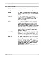
Screens
The CS Series uses a DSP based data acquisition system to provide extensive information
regarding the output of the Source. This data acquisition system digitizes the voltage and current
waveforms and calculates several parameters from this digitized data. The results of these
calculations are displayed in a series of measurement data screens. A total of three
measurement screens are used to display all this information.
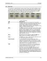
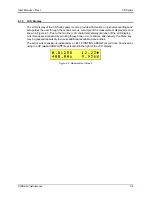
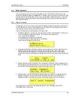
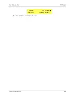
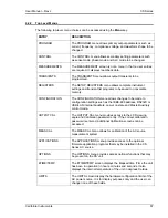
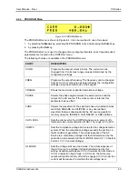
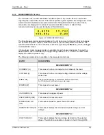
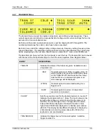
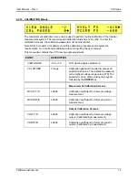
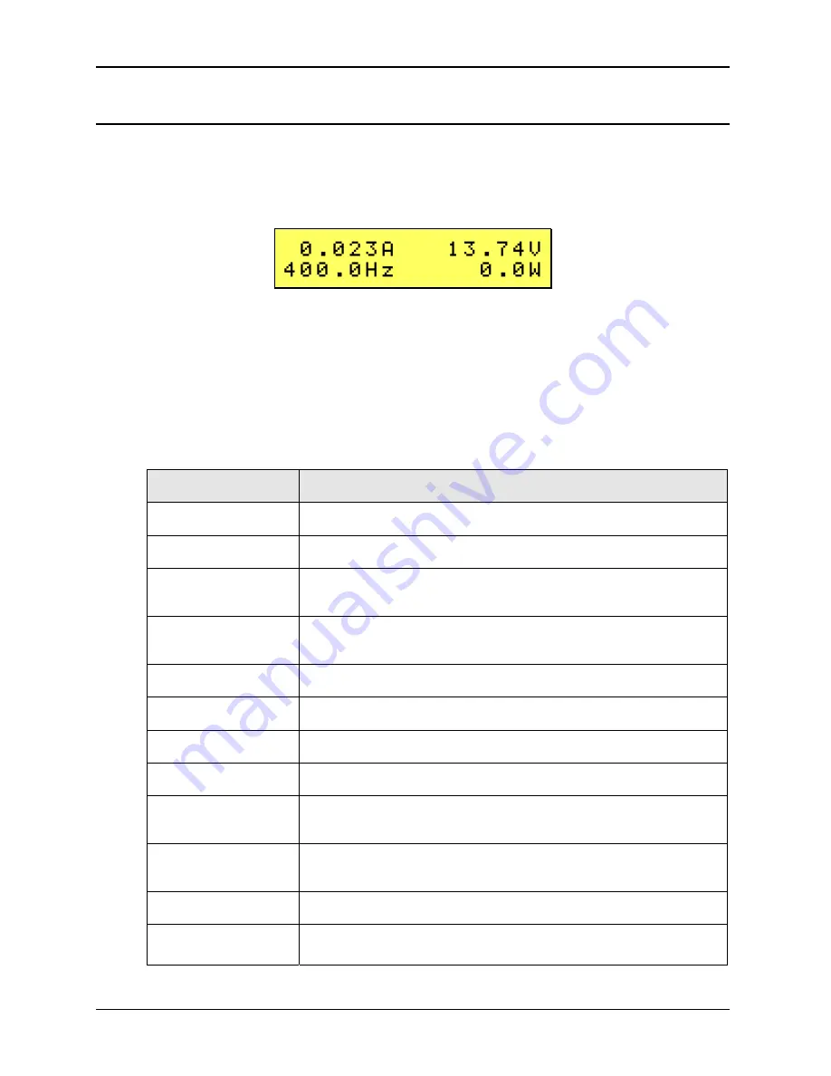
Figure 4-6: MEASUREMENT Screen
The three Measurement screens available on the CS Series are not menus in that no changes
can be made anywhere. Instead, these three screens provide load parameter readouts. The
measurement screens can be reached by successively pressing the
Meas
key, which will toggle
to all available screens
In three-phase mode, measurements are available for each phase individually. To select the
desired phase, use the PHASE key to toggle through phase A, B, C, or ABC. The ABC mode
displays the data for phase A only.
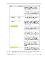
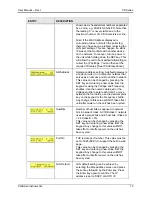
The following parameters are available in the measurement screens:
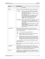
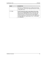
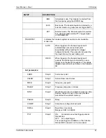
ENTRY
DESCRIPTION
MEASUREMENTS
1
CURRENT (A)
This value is the true rms output current drawn by the load.
VOLTAGE (V)
This value is the true rms output voltage measured at the voltage
sense lines.
FREQ (Hz)
The output frequency is measured at the sense lines.
For CS units with –LKS option, see note below
.
POWER (W)
This value is the real power.
MEASUREMENTS
2
VA POWER (VA)
This value is the apparent power.
VAR POWER (VAR)
This value is the reactive power.
POWER FACTOR
(PF)
This readout shows the power factor of the load.
CREST FACTOR (CF) This readout displays the ratio between peak voltage and rms
voltage.
MEASUREMENTS
3
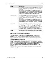
VOLT THD (%V)
This readout displays the total voltage distortion for the selected
phase. The distortion calculation is based on the H2 through H50

