Service & Parts
|
8-7
NOTE
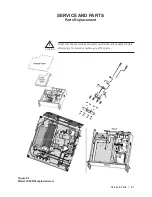
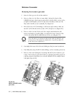
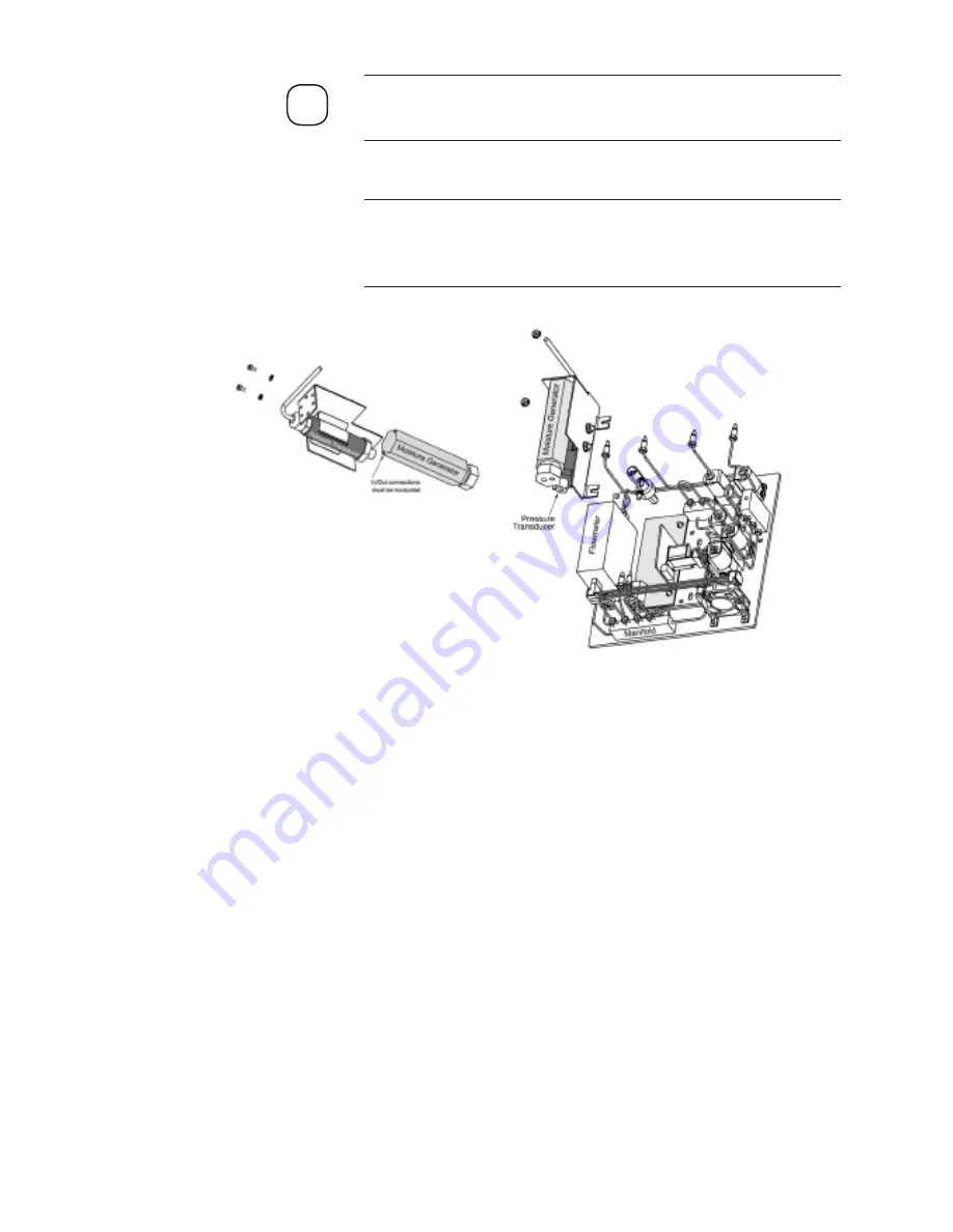
Note the position of the moisture generator in the bracket and how it
is oriented to the mounting screws and the gas connections.
8. Remove the old generator from the bracket, and set it aside.
Use caution when disconnecting the moisture generator and pressure
transducer from the sample system. The tubes are delicate and care
should be taken not to transfer torque to them.
Installing the new moisture generator
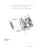
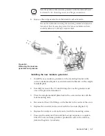
1. Install the new moisture generator on the mounting bracket in the
correct orientation (Figure 8-6) and remount the bracket on the sample
manifold plate.
2. Carefully reconnect the 1/16 inch fittings (two on the generator and
one on the pressure transducer).
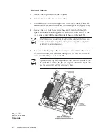
3. Place the sample manifold plate back in the oven and secure with the
four mounting nuts.
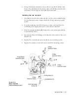
4. Reconnect all four 1/16 fittings on the bracket in the center of the oven.
5. Replace the oven lid, and secure it with the two nuts (Figure 8-1).
6. Replace the analyzer cover and secure it with the mounting screws.
7. Power up the analyzer. Wait until the boot-up sequence is complete.
Enter the new moisture generator production code in the software
(refer to Chapter 4 for details).
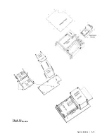
Figure 8-6.
Removing the moisture
generator and pressure
Summary of Contents for 3050-RM
Page 11: ... xi ...
Page 20: ...1 8 3050 RM Moisture Analyzer This page intentionally left blank ...
Page 24: ...2 4 3050 RM Moisture Analyzer This page intentionally left blank ...
Page 27: ...Installation Start Up 3 3 Figures 3 1c Model 3050 RM dimensions top and sides ...
Page 44: ...4 2 3050 RM Moisture Analyzer Figure 4 2 Menu map for 3050 RM Moisture Analyzer ...
Page 63: ...Serial Communications 5 7 Figure 5 6 Defined Failure Codes ...
Page 64: ...5 8 3050 RM Moisture Analyzer Figure 5 7a Variable Table ...
Page 65: ...Serial Communications 5 9 Figure 5 7b Variable Table ...
Page 66: ...5 10 3050 RM Moisture Analyzer This page intentionally left blank ...
Page 78: ...7 2 3050 RM Moisture Analyzer This page intentionally left blank ...
Page 91: ...Service Parts 8 13 Figure 8 9 Electronic Module ...
Page 98: ...PPmV Centigrade Fahrenheit lbs mnscf mg Nm3 ppmW ...

