xvi
M380056-01 Rev L
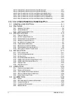
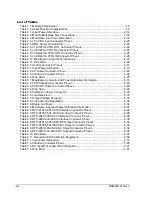
Figure 6 9. RFP-D1016-021-XXXX DC Output Connector, Front Panel View and Wiring Diagram ....... 6-31
Figure 6 10. RFP-D1065-5A1-XXXX DC Output Connector, Front Panel View, and Wiring Diagram ... 6-32
Figure 6 11. RFP-2033-030-XXXX DC Output Connector, Front Panel View, and Wiring Diagram ....... 6-34
Figure 6 12. RFP-2450-2A3-XXXX DC Output Connector, Front Panel View, and Wiring Diagram ...... 6-35
Figure 6 13. Programmable DC Module Front Panel (RFP-D1065-5A1-XXXX shown) ........ 6-40
Figure 6 14. CV and CC Regulation ....................................................................................... 6-43
Figure 6 15. Standalone Output Configuration ....................................................................... 6-45
Figure 6 16. Parallel Output Configuration ............................................................................. 6-46
Figure 6 17. Series Output Configuration ............................................................................... 6-48
Figure 6 18. Series/Parallel Output Configuration .................................................................. 6-50
Figure 6 19. Calibration Instrumentation Setup ..................................................................... 6-59
Figure 7 1. LPAL (375W) Front Panel ...................................................................................... 7-4
Figure 7 2. HPAL (750W) Front Panel ...................................................................................... 7-5
Figure 7 3. Typical Active Load Rear Panel ............................................................................. 7-6
Figure 7 4. Module Installation (example shows 1-U-wide power supply) ............................. 7-15
Figure 7 5. Slot Numbering Assignment, Empty Mainframe Front View ................................ 7-17
Figure 7 6. Interface Connector, Front Panel View, and Wiring Diagram .............................. 7-20
Figure 7 7. DC Input Connector and Wiring Diagram............................................................. 7-21
Figure 7 8. Active Load Front Panel (375W shown)............................................................... 7-25
Figure 7 9. Standalone Input Configuration ............................................................................ 7-27
Summary of Contents for Elgar ReFlex Power
Page 1: ...M380056 01 Rev L www programmablepower com ReFlex Power Operation Manual...
Page 2: ......
Page 3: ......
Page 4: ......
Page 6: ...ii This page intentionally left blank...
Page 8: ...iv This page intentionally left blank...
Page 10: ...vi This page intentionally left blank...
Page 21: ...M380056 01 Rev L xvii This page intentionally left blank...
Page 22: ......
Page 85: ...ReFlex Power Controller ReFlex Power 3 22 M380056 01 Rev L This page intentionally left blank...
Page 89: ...AC Power Supplies ReFlex Power 4 4 M380056 01 Rev L Figure 4 1 ACPS Module Front Panel 875VA...
Page 120: ...ReFlex Power AC Power Supplies M380056 01 Rev L 4 35 Figure 4 11 Parallel Output Configuration...
Page 147: ...AC Power Supplies ReFlex Power 4 62 M380056 01 Rev L RST n...
Page 157: ...AC Power Supplies ReFlex Power 4 72 M380056 01 Rev L 26 Reset the unit RST n...
Page 274: ...ReFlex Power DC Power Supplies M380056 01 Rev L 6 71 18 Turn off the output RST n...
Page 275: ...DC Power Supplies ReFlex Power 6 72 M380056 01 Rev L This page intentionally left blank...
Page 279: ...Active Loads ReFlex Power 7 4 M380056 01 Rev L Figure 7 1 LPAL 375W Front Panel...
Page 280: ...ReFlex Power Active Loads M380056 01 Rev L 7 5 Figure 7 2 HPAL 750W Front Panel...
Page 281: ...Active Loads ReFlex Power 7 6 M380056 01 Rev L Figure 7 3 Typical Active Load Rear Panel...
Page 359: ...Active Loads ReFlex Power 7 84 M380056 01 Rev L This page intentionally left blank...


