ReFlex Power™
Mainframe
M380056-01 Rev L
2-15
2.4.6
AC/DC
I
NPUT
O
VERCURRENT
P
ROTECTION
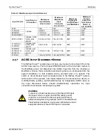
The Mainframe distributes the input power through backplane connectors to
three groups of four slots connected in parallel. Each group is connected to a
separate pair of pins of the input connector (one line and return per connection);
the connector has six power pins plus ground. To properly size the current rating
of the disconnect device, the total load current that will be drawn from an input
line must be determined based on the location of modules within a Mainframe.
The backplane connector from which a module will draw input current is also
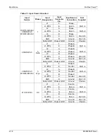
dependent on the width of the module. Table 2-2 presents the number of slots
that a particular module will occupy, to which slot the module will be connected to
draw input power, and the maximum current that the module will draw.
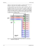
For example, a Mainframe with six HPDC modules (each 2U wide) would have
modules plugged into the following locations: slot 2, slot 4, slot 6, slot 8, slot 10,
and slot 12 (see Figure 2-5). The slots would be connected to the input
connector, as follows: line L1 connected to slots 2 and 4, line L2 connected to
slots 6 and 8, and line L3 connected to slots 10 and 12. If the modules supplied
full rated output power, and the AC input were three-phase, wye with nominal
230/400VAC, each input line would supply 10.8A.
As another example, a Mainframe with four AC power modules would have
modules plugged into the following locations: slot 3, slot 6, slot 9, and slot 12.
The slots would be connected to the input connector, as follows: line L1
connected to slot 3, line L2 connected to slot 6, and line L3 connected to slots 9
and 12. The input current would not be balanced from a three-phase source. If
the modules supplied full rated output power, and the AC input were three-phase,
wye with nominal 230/400VAC, lines L1 and L2 would each supply 5.4A, but line
L3 would supply 10.8A.
Summary of Contents for Elgar ReFlex Power
Page 1: ...M380056 01 Rev L www programmablepower com ReFlex Power Operation Manual...
Page 2: ......
Page 3: ......
Page 4: ......
Page 6: ...ii This page intentionally left blank...
Page 8: ...iv This page intentionally left blank...
Page 10: ...vi This page intentionally left blank...
Page 21: ...M380056 01 Rev L xvii This page intentionally left blank...
Page 22: ......
Page 85: ...ReFlex Power Controller ReFlex Power 3 22 M380056 01 Rev L This page intentionally left blank...
Page 89: ...AC Power Supplies ReFlex Power 4 4 M380056 01 Rev L Figure 4 1 ACPS Module Front Panel 875VA...
Page 120: ...ReFlex Power AC Power Supplies M380056 01 Rev L 4 35 Figure 4 11 Parallel Output Configuration...
Page 147: ...AC Power Supplies ReFlex Power 4 62 M380056 01 Rev L RST n...
Page 157: ...AC Power Supplies ReFlex Power 4 72 M380056 01 Rev L 26 Reset the unit RST n...
Page 274: ...ReFlex Power DC Power Supplies M380056 01 Rev L 6 71 18 Turn off the output RST n...
Page 275: ...DC Power Supplies ReFlex Power 6 72 M380056 01 Rev L This page intentionally left blank...
Page 279: ...Active Loads ReFlex Power 7 4 M380056 01 Rev L Figure 7 1 LPAL 375W Front Panel...
Page 280: ...ReFlex Power Active Loads M380056 01 Rev L 7 5 Figure 7 2 HPAL 750W Front Panel...
Page 281: ...Active Loads ReFlex Power 7 6 M380056 01 Rev L Figure 7 3 Typical Active Load Rear Panel...
Page 359: ...Active Loads ReFlex Power 7 84 M380056 01 Rev L This page intentionally left blank...


