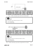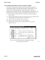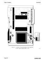
Page 11
User Guide
Signal Processor
LMG GS
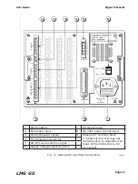
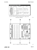
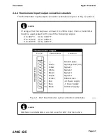
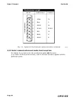
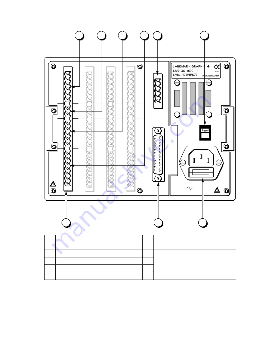
Fig. 4 - Rear panel electrical connections
238004
1
2
3
4
5
6
9
8
7
THERMOMETER
R
ALARMS
S
100 - 120V
200 - 240V
50-60Hz
35VA MAX.
T 1A 250V
RS 232C
RS 485
1
2
3
4
5
OUTPUT
T
CMD
D
1
2
3
4
5
6
1
2
1
2
3
4
5
1
2
3
4
5
6
7
1
2
3
4
5
6
1
2
1
2
3
4
5
1
2
3
4
5
6
7
9
10
1
2
3
4
5
6
1
2
1
2
3
4
5
1
2
3
4
5
6
7
9
10
1
2
3
4
5
6
1
2
1
2
3
4
5
1
2
3
4
5
6
7
9
10
A
B C D
1
Alarm output
7
AC power input
2
Command input
8
RS 232C serial comms input
3
Retransmission output
9
Channel A* terminal block
(* Channels B,C & D may not
be identical to A, dependent on
types of thermometers to be
connected)
4
Thermometer connector
5
RS 485 serial comms output
6
Supply voltage selector switch
Summary of Contents for Land LMG GS
Page 2: ......
Page 6: ......
Page 8: ......
Page 12: ...Page 4 Signal Processor User Guide LMG GS...
Page 35: ...Page 27 User Guide Signal Processor LMG GS Fig 20 Access code display 238020...
Page 62: ......


