Page 23
User Guide
Signal Processor
LMG GS
3 Using the Processor
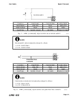
Once the processor has been installed in its chosen location, it must be connected
to the appropriate thermometer(s) and to a suitable a.c. power supply.
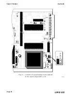
Ensure that the supply voltage setting switch, located on the rear panel of the
processor, is set to correspond with your processor power supply.
When the processor is first connected to a thermometer, the processor must be
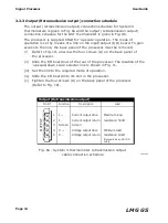
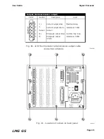
configured for use with that thermometer. Electrical connections to and from the
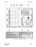
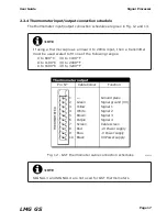
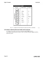
processor are made on the rear panel. The temperature measurement system
(i.e. processor and thermometer) is configured via the processor menu system
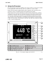
using the keys on the front panel. The location of the processor controls is given
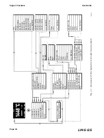
in Fig. 16. An overview of the System 4 and GST I/O card menu systems is given
in Fig. 17 and 18 respectively.
Fig. 16 - Front panel display and controls
238016
1
2
3
4
5
6
7
1
Front display panel
5
Cursor ‘up’ key
2
Emissivity adjustment ‘quick key’
6
Cursor ‘down’ key
3
Alarm adjustment ‘quick key’
7
‘Enter’ key
4
Display selector ‘quick key’
Summary of Contents for Land LMG GS
Page 2: ......
Page 6: ......
Page 8: ......
Page 12: ...Page 4 Signal Processor User Guide LMG GS...
Page 35: ...Page 27 User Guide Signal Processor LMG GS Fig 20 Access code display 238020...
Page 62: ......

