3 - 7
Installation Guide
SDS
Slag Detection System
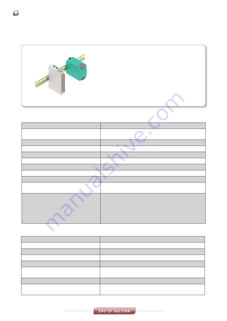
3.5 IO Module
Fig. 3-8 IO Module & PSU (DIN Rail mounted)
Specifications - IO Module
Mountings
DIN Rail
Connections
AC Mains Power In
Ethernet to Process Imaging Workstation
Breakdown Voltage
500 VAC
Contact Current Rating Resistive load 5 A @ 30 VDC, 250 VAC, 110 VAC
Contact Resistance
100 milli-ohms (max.)
Initial Insulation Resistance
1,000 mega-ohms (min.) @ 500 VDC
Dimensions
27.8 x 124 x 84 mm / 1.09 x 4.88 x 3.31 in
Weight
200 g / 0.44 lb
Wiring I/O cable
16 to 26 AWG
Operating Temperature Standard
Models
-10 to 60 °C (14 to 140 °F)
Storage Temperature (package
included)
-40 to 85 °C (-40 to 185 °F)
Note: Ambient humidity must be non-condensing
and remain between 5 and 95 %.
The relays may malfunction when operating in
high condensation environments below 0 °C /
32 °F.
Features
•
DIN Rail Mounted
•
Must be installed inside an enclosure
Specifications - IO Module Power Supply
AC-Input Voltage
AC 100-240 V (-15%/+10%)
Input current
<0.6A (@ AC 100 V, 30 W Pout)
External Input Fuse Recommendation Minimum B-10A / C-6A
Dimensions (WxHxD)
45 x 75 x 91 mm /
Weight (excluding packing)
230 g / 0.5 lb
Connector Size Range
Flexible cable 0.3 - 2.5 mm
2
(28-12 AWG)
Ferrules admissible
Operating Temperature Range
-10 to +70 °C / -14 to +158 ° F
Storage & Transport Temperature
Range
-25 to +85 °C / -13 to +185 ° F
Summary of Contents for Land SDS
Page 8: ...3 2 Installation Guide Slag Detection System SDS Fig 3 2 SDS Camera Installation Dimensions ...
Page 24: ...Slag Detection System SDS APPENDIX CONDUIT INSTRUCTIONS Installation Guide Appendix ...
Page 25: ......
Page 26: ...Slag Detection System SDS ...
Page 27: ...SDS Slag Detection System ...


