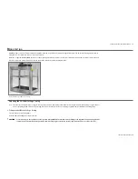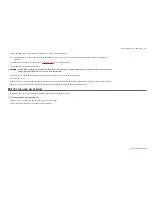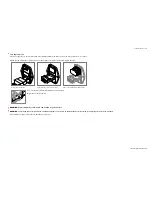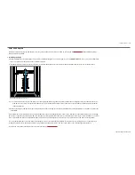
Setting Up the Machine and Hardware
10
LD Series Operation Manual
3
Follow the fitting and wiring instructions for the Console and Emergency Stop Buttons.
Note:
The positioning of controls is the responsibility of the final user, who should ensure (as part of the Risk Assessment) that sufficient stop buttons are
provided.
4
Lift the LD Series onto the mounting frame. See
Lifting on page 8
for proper lifting methods.
5
Secure the LD Series to the mounting frame.
!
CAUTION:
Because the mounting plates protrude from the bottom of the machine, no attempt should be made to stand the machine on its own. It will
only be stable when it is fitted and secured to the mounting frame.
6
Insert the Pogo rod through the bearing on the lower (fixed) crosshead, and connect to the bottom platen.
7
Connect the load cell.
Once the LD Series is installed, wired, and ready for use, the user must conduct the final Risk Assessment of the machine, including all safety measures (shield,
guard, etc.) to satisfy the requirements of the Machinery Directive and EHSR (Essential Health and Safety Requirements).
FITTING THE HAND-HELD REMOTE
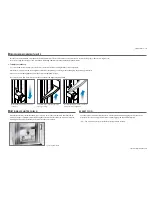
The height of the console can be adjusted to give the best position for viewing and operation.
X
To Connect the Remote to the LD Series
1
Plug the connector attached to the remote into the rear of the machine.
2
Adjust the height of the remote using the position locking lever.


