background image

Overview 


4

LD Series Operation Manual

„„„„

„

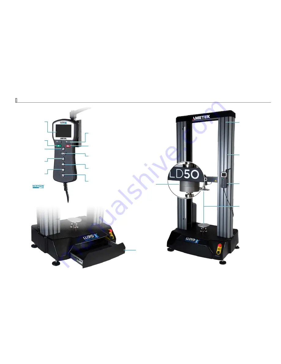
MAIN COMPONENTS

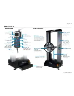
Handheld Controller

Assemblies and Features

F1 and F2

Soft keys which access the
menu options on the display.

Back to Zero

Returns the crosshead to the
starting zero point.

Stop

Stops the test.

Start

Starts the test.

Display

Shows the current force

applied and the crosshead

position.

Slow Jog Up

Slowly moves the crosshead
up to a desired position.

Fast Jog Down

Quickly moves the crosshead
down to a desired position.

Zero

Sets the zero position

at the beginning of a test.

Fast Jog Up

Quickly moves the crosshead

 up to a desired position.

Slow Jog down

Slowly moves the crosshead

 down to a desired position.

The jog speeds can be configured using
the Nexygen

Plus 

4 software.

Easy Grip

Alignment

With our unique system, 
fixture and grip alignment 
is quick and easy.

Low-profile, Rugged Base

Our low-profile base provides a large 
working area.

Easy Mounting

T-slots are molded into
the aluminum frames to 
accept accessories like 
extensometers, splinter 
shields, and robot arms.

Handheld Controller

See details at left.

Machine Stiffness

Rigid construction 
provides minimal 
deflection in the frame 
and crosshead.

Drawer

A built-in drawer provides
a space for tool storage.

Optional Pancake

Load Cells

Optional pancake load cells 
improve accuracy at the cross 
axis and help increase work area.

Adherent to

International Standards

The mechanical design of the LD Series 
adheres to International standards for 
industries including metal, composites, 
automotive, building materials, medical 
devices, and packaging.

Summary of Contents for LD10

Page 1: ...LD Series Operation Manual Dual Column Test Stand LD5 LD10 LD30 LD50 LD100 Models ...

Page 2: ... Up the Machine and Hardware 7 Unpacking 7 Setting Up the LD Series 7 Lifting 8 Lifting With a Pallet 8 Lifting With Straps 8 Lifting With a Forklift 8 Securing the LD Series to a Bench 8 POGO Testing 9 Preparing the LD Series for Pogo Testing 9 Fitting The Hand Held remote 10 Mains Input Voltage Selection 11 Load Cells and Grips 13 Grips and Adapters 14 Specifications 15 Support 17 Contact Us 17 ...

Page 3: ...ING Hazard Protect electrical cables from damage and inadvertent disconnection The loss of controlling and feedback signals that can result from a disconnected or damaged cable causes an open loop condition that may drive the actuator or crosshead rapidly to its extremes of motion Protect all electrical cables particularly transducer ca bles from damage Never route cables across the floor without ...

Page 4: ...nd use protective shields or screens whenever a risk of injury to operators and observers exists from the failure of a test specimen assembly or struc ture particularly where explosive disintegration may occur Due to the wide range of specimen materials assemblies or structures that may be tested any hazard resulting from the failure of a test specimen assembly or structure is entirely the respons...

Page 5: ...junction with NexygenPlus 4 a Microsoft Windows application NexygenPlus 4 uses familiar Windows user controls helping an operator quickly learn the system and feel comfortable performing a wide range of tasks Data from NexygenPlus 4 can be exported to Microsoft Excel or Mi crosoft Word for further manipulation and enhanced presentation NexygenPlus 4 software contains a library of pre programmed te...

Page 6: ...ds can be configured using the NexygenPlus 4 software Easy Grip Alignment With our unique system fixture and grip alignment is quick and easy Low profile Rugged Base Our low profile base provides a large working area Easy Mounting T slots are molded into the aluminum frames to accept accessories like extensometers splinter shields and robot arms Handheld Controller See details at left Machine Stif...

Page 7: ... the crosshead motor circuit is ready but not powered The safe line circuit must be activated before the material tester can be used Pressing the safe line button will turn the light off to indicate that the material tester is now ready for use Use the main power switch to turn power off when the material tester is not in use Safe Line Button Main Power Switch The Safe Line button The Main Power s...

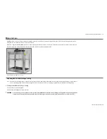
Page 8: ...step 2 4 Loosen the screw and move it to the cross head actuator and tighten in this position Move the Limit Stop to the top or bottom drive the Moving Crosshead to a position then move the Limit Stop to the Crosshead of its travel it may go to safely Actuator position and tighten it OPTIONAL SPLINTER SHIELD A transparent splinter shield is available as an option to enclose the test sample A shiel...

Page 9: ...ent may be impaired The LD Series should be in stalled in an area where adequate lighting is present in order to ensure safe use Ensure adequate ventilation Do not block airflow to fans or vents on the enclosure Note Do not position the LD Series so that it is difficult to operate The mains supply machine socket should be easily accessible so that the mains power may be disconnected in case of an ...

Page 10: ...nection socket Lifting With a Forklift An alternative method for lifting is the use of a forklift truck with the forks under the moving crosshead Ensure the crosshead is well padded to avoid damage to the machine Ensure the forks do not damage the load cell socket SECURING THE LD SERIES TO A BENCH The materials tester is heavy and cannot normally tip over However if there is the possibility that u...

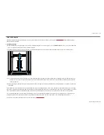
Page 11: ... an LD Series on a Pogo Preparing the LD Series for Pogo Testing Note Since the size and specifications of Pogo mounting frames will vary depending on individual customer requirements the following is a general proce dure for preparing the LD Series for Pogo testing Refer to the instructions for set up and wiring supplied with your individual mounting frame X X To Prepare the LD Series for Pogo Te...

Page 12: ...ts own It will only be stable when it is fitted and secured to the mounting frame 6 Insert the Pogo rod through the bearing on the lower fixed crosshead and connect to the bottom platen 7 Connect the load cell Once the LD Series is installed wired and ready for use the user must conduct the final Risk Assessment of the machine including all safety measures shield guard etc to satisfy the requireme...

Page 13: ...cover over the terminal strip and identify the four terminals on the left end of the terminal strip located on the back of the machine Rubber mat removed for clarity 2 opposite side Location of Terminal Strip Remove the 13 screws to remove the rear plastic housing shroud then remove the terminal strip protective cover 3 To configure for 115 volt mains configure the two jumpers between the outer sc...

Page 14: ...emove power to the unit Open the voltage selector access panel Remove the voltage selector fuse holder 115V 2 3 0 V Note The fuses must be installed with one end touching the pin end of the fuse holder WARNING Replace with Bel Fuse 5SF P 10 R 10A 250VAC or equivalent fuse WARNING To avoid the risk of electrical shock equipment must be connected to an outlet with a protective earth ground using the...

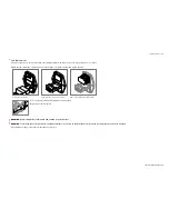
Page 15: ...n the load cell fits in one of the holes on the underside of the moving crosshead Place the adapter into the moving crosshead then screw the adapter into the load cell 4 Check that the connecting cable is on the same side as the connecting socket then tighten the load cell adapter with the C spanner provided 5 Insert the load cell plug in the socket on the rear of the moving crosshead and finger t...

Page 16: ...is fixed in position so that it does not block the normal downward movement of the upper fixture Avoid overloading beyond the rated capacity of the load cell Prior to testing ensure that the maximum force anticipated will not exceed the capacity of the cell installed Lloyd Instruments load cells are built to exceed the standards as set out by ASTM BS DIN etc Load cells on all models of LD Series m...

Page 17: ...n LD100 325 mm min 10 in min Speed Accuracy 0 1 Crosshead Travel Standard Height 1070 mm 42 in Extended Height 1669 mm 65 7 in The LD100 is available in only a standard height version Extension Resolution LD5 10 0 000354 micron per encoder count LD30 0 000214 micron per encoder count LD50 0 000121 micron per encoder count LD100 0 000063 micron per encoder count Load Cell Load Cell Accuracy 0 5 of ...

Page 18: ...04 F Sound Pressure Level 70 dB A Control Modes Position Load Rate and Strain Rate Control Software NexygenPlus 4 Ratings Mains Supply Voltage Fluctuations not exceeding 10 of the nominal voltage Transient Overvoltages According to overvoltage category II Maximum Relative Humidity 80 for temperatures up to 31 C Altitude Up to 2000 m Indoor use only Pollution degree 2 ...

Page 19: ...e option repair or replace the instrument or any part thereof which is defective provided however that this warranty shall not apply to instruments subjected to tampering or abuse or exposed to highly corrosive conditions THISWARRANTY IS IN LIEU OF ALL OTHERWARRANTIESWHETHER EXPRESS OR IMPLIED AND AMETEK HEREBY DISCLAIMS ALL OTHERWARRANTIES INCLUDING WITHOUT LIMITATION ANY WARRANTY OF FITNESS FOR ...

Page 20: ...5777 A 2017 AMETEK Incorporated ...

Reviews: