SXRXLXX1 - SIL IntelliPoint RF Series User's Manual
24
4.3
Over Range
If the Red LED is flashing quickly (4 times/second), IntelliPoint
has detected that uncovered sensing element capacitance
exceeds limits of transmitter. Consult factory for pad capacitor
values and instructions.
4.4
Under Range
If the Red LED is flashing slowly (once per second), IntelliPoint
has detected that pad capacitor value is too large or a center wire
to Cote Shield short. Consult factory for pad capacitor values.
4.5
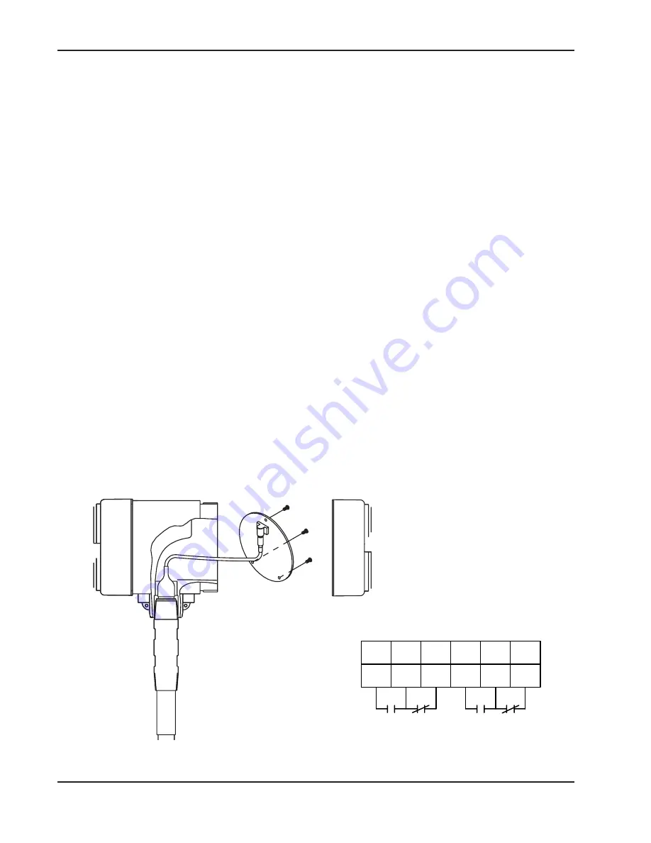
Testing the Relay Circuits
Use the following steps to check out the relay circuits:
A. Relay circuits consist of a single-pole double-throw relay
contacts brought out to terminal strips for external
switching. See
Figure 4-1.
B. Relay operation may generally be heard as an audible click
when background noise is not too high. Connect ohmmeter
to relay contacts to determine if they are switching.
C. Move the fail safe jumper to th eopposite position. The red
LED will change and relay contacts should also change. If the
contacts do not change, the relay is not functioning properly.
Figure 4-1
Relay Circuit Operation
Customer
Connections
View
3
5
6
4
7
8
NO
NC NO
C
C
NC
Summary of Contents for SIL IntelliPoint RF S*R*L Series
Page 4: ...Contents...
Page 6: ...Section 1...
Page 38: ...SXRXLXX1 SIL IntelliPoint RF Series User s Manual 32 Section 5...
Page 41: ...Specifications 35 Section 6...
Page 43: ...Control Drawings 37 6 1 FM FMc Control Drawings Continued...
Page 44: ...SXRXLXX1 SIL IntelliPoint RF Series User s Manual 38 6 1 FM FMc Control Drawings Continued...
Page 45: ...Control Drawings 39 6 1 FM FMc Control Drawings Continued...
Page 46: ...SXRXLXX1 SIL IntelliPoint RF Series User s Manual 40 6 1 FM FMc Control Drawings Continued...
Page 47: ...Control Drawings 41 6 1 FM FMc Control Drawings Continued...
Page 48: ...SXRXLXX1 SIL IntelliPoint RF Series User s Manual 42 6 1 FM FMc Control Drawings Continued...
Page 56: ...SXRXLXX1 SIL IntelliPoint RF Series User s Manual 50 6 2 ATEX Control Drawings...
Page 57: ...Control Drawings 51 6 2 ATEX Control Drawings Continued...
Page 66: ...SXRXLXX1 SIL IntelliPoint RF Series User s Manual 60 6 4 IECEx Control Drawings...
Page 67: ...Control Drawings 61 6 4 IECEx Control Drawings Continued...
Page 75: ...Control Drawings 69 6 5 Mounting and Wiring for Spark Protector Drawings...
Page 77: ...Control Drawings 71 6 5 Mounting and Wiring for Spark Protector Continued...
Page 78: ...SXRXLXX1 SIL IntelliPoint RF Series User s Manual 72 6 6 Adding a Padded Capacitor...
Page 79: ...Control Drawings 73 6 6 Adding a Padded Capacitor Continued...
Page 80: ...SXRXLXX1 SIL IntelliPoint RF Series User s Manual 74 6 6 Adding a Padded Capacitor Continued...
Page 81: ...Control Drawings 75 6 7 Dual Seal Assembly for 700 Series Sensing Elements...
Page 82: ...SXRXLXX1 SIL IntelliPoint RF Series User s Manual 76 6 7 Dual Seal Assembly Continued...
Page 83: ...Control Drawings 77 6 7 Dual Seal Assembly Continued...
Page 84: ...Appendix A...
Page 88: ...SXRXLXX1 SIL IntelliPoint RF Series User s Manual A 4 Appendix B...
Page 90: ...SXRXLXX1 SIL IntelliPoint RF Series User s Manual B2 EXIDA Report Results...


