Asterion DC Multioutput ASA Series Operational Manual
M330516-01
3-70
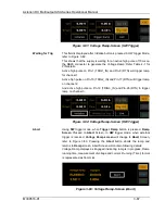
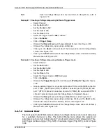
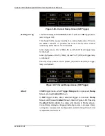
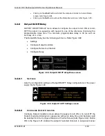
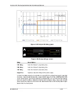
Figure 3-86-: Current Ramp-Screen (SW Trigger)
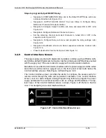
Waiting for Trig
This field is displayed after
Initialize
button is pressed in
HW
trigger Mode,
refer to Figure 3-87:.
This shows that the supply is waiting for an active high pulse of 10ms on
the DB26 connector to generate the Current Ramp each channel
individually. Refer Table 4-1 for PIN details.
Active high pulse on
Pin-1 (TRIG1_IN) and Pin-8 (RTN) will trigger ramp
for channel 1,
Active high pulse on Pin-10 (TRIG2_IN) and Pin-17 (RTN) will trigger ramp
on channel 2,
And active high pulse on Pin-19 (TRIG3_IN) and Pin-26 (RTN) to trigger
ramp on channel 3.
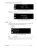
Figure 3-87: Current Ramp-Screen (HW Trigger)
Abort
In
SW
trigger mode, when
Trigger Ramp
button is pressed,
Ramp
Screen proceed to
Abort
Screen.
In
HW
trigger mode,
when
external trigger is received,
Ramp
Screen
will Proceed to
Abort
Screen
,
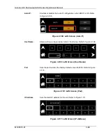
refer to Figure 3-88. Pressing
the
Abort
button aborts the ramp and returns to Ramp screen.
Current Ramp displays as Engaged indicating ramp is in progress, Ramp
running time, measurement of voltage and current. Running (Timer) format
is represented as hh:mm:ss.


