DC Asterion Series
Overview
M330460-01 Rev A
2-19
Remote Analog
Programming of
Overvoltage
Signal input for setting Overvoltage using External Analog Reference Voltage.
Range: 0.25 V to user selectable maximum range (2 V to 10 V) for 5% to 110% of the full-
scale Output Voltage.
Programming accuracy and linearity: ±1% of full-scale output
Monitor Signals
for the Output
Voltage, Current
and Power
Monitor Signals for the Output Voltage, Current and Power.
Full Scale range: 0 V to 10 V corresponds to 0-100% full-scale output
Minimum recommended Load: 100 kΩ, typical
Maximum Load: 20 kΩ
Monitor accuracy: ±1% of full-scale output
Remote ON/OFF
Control input for Output ON/OFF
Switch/Relay contact closure or direct short-circuit from this terminal to signal return will
enable (turn-on) the output of the supply
Remote circuit must sink up to 3 mA from 5 VDC to enable.
Isolated Remote
ON/OFF Control
There are two types of isolated control inputs to turn ON/OFF power supply
a) Isolated remote-control input for output on/off with an applied AC/DC voltage
source. A positive (+) 6-120 VDC or an AC input of 12- 240 VAC will enable (turn-
on) the output of the supply.
b) Isolated remote-control input for output on/off with a logic signal: a logic-high, 5
VDC TTL/CMOS signals will enable (turn-on) the output of the supply, and a logic-
low signal disables (turns off) the output
Note: These control input is optically isolated from the output power negative terminal of
the power supply (up to 500 VDC).
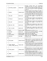
TRIGGER IN
Input signal, TTL active-high; provides external hardware triggering of voltage and current
ramp functions
Signal connects to Open-anode of opto-
isolator diode with internal 1kΩ series resistor
internal to power supply
Voltage Rating: Maximum 24 V, Minimum -5V
Low state 0.3 V max, High State 2.7 V min.
TRIGGER OUT
Output signal, active-low; synchronization pulse of 10 ms when a change in the output
occurs. There is an Option to feed User Power to the TRIGGER OUT signal.
Internal to power supply, signal output is from driver with input connected to open-collector
of opto-isolator transistor
Voltage Rating: Maximum 30 V, Minimum 4.5V for Active High, Current Maximum 0.5 A
FAULT
Output Signal, High state indicates fault state of the power supply. There is an Option to
feed User Power to the FAULT signal.
Internal to power supply, signal output is from driver with input connected to open-collector
of opto-isolator transistor
Voltage Rating: Maximum 30 V, Minimum 4.5V for Active High, Current Maximum 0.5 A
User
programmable
digital inputs
Four digital inputs to the power supply. Two of the digital inputs can be used as enable
signals for user programmable digital outputs.
Signal connects to Open-anode of opto-isolator diode with
internal 1kΩ series resistor
internal to power supply
Voltage Rating: Maximum 24 V, Minimum -5V
Low state 0.3 V max, High State 2.7 V min
User
programmable
digital outputs
Four digital outputs that can be enabled/ disabled from the power supply. Two digital
outputs can be controlled by giving appropriate signals on User programmable digital
inputs. There is an Option to feed User Power to these digital outputs.
Voltage Rating: Min 4.5V or User fed voltage minus 1 V. User fed voltage can be of
maximum 30 V.
Summary of Contents for Sorensen Asterion AST Series
Page 1: ...M330460 01 Rev A www powerandtest com DC Asterion 1U Operation Manual ...
Page 2: ......
Page 26: ......
Page 53: ...DC Asterion Series Overview M330460 01 Rev A 2 27 This page intentionally left blank ...
Page 54: ......
Page 109: ...DC Asterion Series Overview M330460 01 Rev A 3 55 This page intentionally left blank ...
Page 110: ......
Page 112: ......
Page 117: ...DC Asterion Series Index M330460 01 Rev A 3 ...
Page 118: ...Maintenance DC Asterion Series 4 M330460 01 Rev A This page intentionally left blank ...


