Overview
DC Asterion Series
3-40
M330460-01 Rev A
3.3
Remote Analog Programming Connector
The Analog Control connector of the Remote Analog Interface on the rear panel allows
the unit to be configured for different operating configurations: front panel (local) and
remote programming of voltage, current, and OVP, voltage and current monitoring,
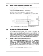
output enable/disable, etc. Refer to Figure 3-97 for the connector pin-out diagram. The
setup and operating requirements of each configuration are provided in Sections 3.4
through 3.8.
The DC Asterion also has the capability of providing summing of remote analog input
with the set values on the front panel (or programmed values via the digital interface)
for voltage, current and Power. This capability provides a means to modulate a set
value with the signal on the voltage, current and Power analog input. If the user only
desires to control the unit with the analog input, all the front panel values (V/I/P) or
digital settings should be set to zero.
CAUTION!
If standard, Remote Non-Isolated Analog Interface programming is used, the
programming return (J1-6 and J1-24) is at the same potential as the negative output
terminal of the power supply (not isolated). Proper connection should be made to
signal returns with respect to input programming equipment. Improper connection
might result in ground/return loops and, as a result, internal power supply damage
might occur; output current could then flow by way of the external connection to the
J1 common (J1-6 and J1-24). Refer to Table 3
3.3.1
Remote Analog Isolated Interface Control (Option)
The Remote Isolated Analog Interface control uses the same Analog Control
connector (J1) as the standard interface. This option fully isolates remote control
signals and allows control of units not connected to a common ground. Control ground
is isolated from
output power (output negative terminal), which protects against
potential damage from systems with high electrical noise or large ground loop currents.
Note:
Some standard, Non-Isolated Analog Interface programming signals are not
available with this option; see Table 3
–2 for details.
CAUTION!
The Remote Isolated Analog Interface option is not intended to allow operation of
the power supply at excessive voltages. Operation of Isolated Analog Interface
signals should be at SELV safety voltage conditions to chassis ground. Refer to
section 1.2.2 for maximum terminal voltages.
Summary of Contents for Sorensen Asterion AST Series
Page 1: ...M330460 01 Rev A www powerandtest com DC Asterion 1U Operation Manual ...
Page 2: ......
Page 26: ......
Page 53: ...DC Asterion Series Overview M330460 01 Rev A 2 27 This page intentionally left blank ...
Page 54: ......
Page 109: ...DC Asterion Series Overview M330460 01 Rev A 3 55 This page intentionally left blank ...
Page 110: ......
Page 112: ......
Page 117: ...DC Asterion Series Index M330460 01 Rev A 3 ...
Page 118: ...Maintenance DC Asterion Series 4 M330460 01 Rev A This page intentionally left blank ...


