1
13
14
25
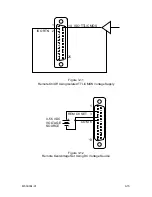
Figure 3-2
Pin-out for Connector J1
The power supply may be configured via
connector J1 on the rear panel for different
operating configurations: local and remote
current programming, local and remote
voltage programming, normal parallel,
auto-parallel, normal series, auto-series,
and auto-tracking. The use and operating
requirements of each configuration are
provided in the following paragraphs.
Reference Table 3-2 for connector J1
designations and functions. See Figure 3-2
for pin-out diagram.
CAUTION:
These control inputs are referenced to the
negative output of the power supply.
Grounding the positive output of the power
supply or biasing the output of the supply
above chassis potential will cause this input
(along with the output of the supply) to
have a potentially hazardous offset voltage.
Exercise caution under these conditions.
3.3 LOCAL
OPERATION
Units are shipped from the factory configured for local voltage/current control and local
voltage sensing. J1 is supplied with a mating connector with remote on/off jumpered for
ON (terminal 5 shorted to terminal 6).
3.4 REMOTE CURRENT PROGRAMMING
The remote current programming is used for applications that require the output current
be programmed (controlled) from a remote source. An external resistance or external
voltage source may be used as a programming device. When using remote current
programming, a shielded, twisted-pair, hookup wire is recommended to prevent noise
interference with programming signals.
1.
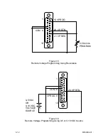
External Current Programming Using Resistance. The resistance coefficient
for remote current programming is 5k ohms/100% rated output with respect
to terminal J1-23 (IP RTN). The programming current from terminal J1-22
(IP RES) is factory set for 1 milliamp. This yields a coefficient of 1.0% of
rated output current for each 50 ohms. If multiple switches or relays are
used to program different levels, make-before-break contacts are
recommended. Note that if an external resistance is used for remote
programming, the current programming return (IP RTN), terminal J1-23,
must be connected directly to or within ±3 volts of the power supply common
terminal, J1-24. See Figure 3-3 for connection requirements.
M550004-01
3-8
Summary of Contents for Sorensen DHP Series
Page 1: ...M550004 01 Rev K www programmablepower com DHP Series DC Power Supplies Operation Manual...
Page 2: ......
Page 3: ......
Page 4: ......
Page 6: ...This page intentionally left blank ii...
Page 8: ...This page intentionally left blank iv...
Page 10: ...This page intentionally left blank WA 2...
Page 44: ...This page intentionally left blank M550004 01 3 16...
Page 54: ...This page intentionally left blank M550004 01 5 6...

