background image

2. 

External Current Programming Using a 0-5 VDC or 0-10 VDC Voltage 
Source.  A DC voltage source for remote current programming is connected 
between J1-10 or J1-16 (IPROG) and the return terminal J1-23 (IP RTN).  
Note that the return terminal J1-23 (IP RTN) must be referenced directly to 
or within ±3V of the power supply common, J1-24.  The voltage coefficient 
for 5V remote current programming is 50 millivolts = 1% of rated output, i.e., 
for a 300 amp model, each 50 millivolts of programming voltage equals 3 
amps of output current.  The voltage coefficient for 10V remote current 
programming is 100 millivolts = 1% of rated output, i.e., for a 300 amp 
model, each 100 millivolts of programming voltage equals 3 amps of output 
current.  See Figure 3-4 for connection requirements. 


3.5  REMOTE VOLTAGE PROGRAMMING 

The remote voltage programming configuration is used for applications that require the 
output voltage be programmed (controlled) from a remote source.  An external 
resistance or external voltage source may be used as a programming device.  When 
using remote voltage programming, a shielded, twisted-pair, hookup wire is 
recommended to prevent noise interference with programming signals. 

 
1. 

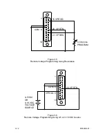
External Voltage Programming Using Resistance.  The resistance coefficient 
for remote voltage programming is 5k ohms/100% of rated output voltage 
with respect to the VP RTN, J1-20.  The programming current from terminal 
J1-21 (VP-RES) is factory set to 1 milliamp.  This yields a coefficient of 1.0% 
of rated output voltage for each 50 ohms.  If multiple switches or relays are 
used to program different levels, make-before-break contacts are 
recommended.  Note that if an external resistance is used for remote 
programming, the voltage programming return (VP RTN), terminal J1-20, 
must be connected directly to or within ±3 volts of the power supply common 
terminal, J1-24   See Figure 3-5 for connection requirements. 

 
2. 

External Voltage Programming Using a 5 VDC or 10 VDC Voltage Source.  
A DC voltage source for remote voltage programming is connected between 
J1-9 or J1-15 (VPROG) and the return terminal J1-20 (VP RTN).  Note that 
the return terminal (VP RTN) must be referenced directly to or within ±3V of 
the power supply common, J1-24.  The voltage coefficient for 5V remote 
voltage programming is 5 volts = 100% of rated output voltage.  The voltage 
coefficient for 10V remote voltage programming is 10 volts = 100% of rated 
output voltage.  To program voltage slightly above the rated output will not 
damage the unit, but degraded performance may result.   See Figure 3-6 for 
connection requirements. 


3.6 REMOTE 

SENSING 

In applications where the load is located some distance from the power supply, or the 
voltage drop of the power output leads significantly interferes with load regulation, 
remote voltage sensing may be used.  When remote sensing is used, voltage is 

M550004-01 


3-9

Summary of Contents for Sorensen DHP Series

Page 1: ...M550004 01 Rev K www programmablepower com DHP Series DC Power Supplies Operation Manual...

Page 2: ......

Page 3: ......

Page 4: ......

Page 5: ...fication purposes only Notice of Copyright DHP Series DC Power Supplies Operation Manual 2002 AMETEK Programmable Power Inc All rights reserved Exclusion for Documentation UNLESS SPECIFICALLY AGREED T...

Page 6: ...This page intentionally left blank ii...

Page 7: ...and equipment safety Always ensure that facility AC input power is de energized prior to connecting or disconnecting any cable In normal operation the operator does not have access to hazardous volta...

Page 8: ...This page intentionally left blank iv...

Page 9: ...nstructions of AMETEK is opened modified or disassembled in any way without AMETEK s consent or is used in combination with items articles or materials not authorized by AMETEK The Buyer may not asser...

Page 10: ...This page intentionally left blank WA 2...

Page 11: ..._______________ 3 8 3 4 REMOTE CURRENT PROGRAMMING __________________________________ 3 8 3 5 REMOTE VOLTAGE PROGRAMMING __________________________________ 3 9 3 6 REMOTE SENSING _____________________...

Page 12: ...uto step Programming Screen 4 1 Figure 4 2 Auto step Programming Menu System 4 2 Figure 4 3 Programming Start Screen 4 3 Figure 4 4 Control Source Menu 4 4 Figure 4 5 Control Source Auto step 4 4 Figu...

Page 13: ...ude three separate series the 2U High the 3U High and the 6U High The power supplies of each series are constant current constant voltage supplies with an automatic crossover feature The 2U High Serie...

Page 14: ...nnections not included 3 50 in 45 lbs max 208 230 VAC tested to 190 253 VAC 47 to 63 Hz Single 2 wire plus ground Three 3 wire plus ground optional 0 1 of max output voltage 0 2 of max output current...

Page 15: ...Temperature Operating Storage Humidity Cooling Agency Approvals excludes 600 volt models 0 5k ohms 0 5k ohms 0 5 10 VDC 0 5 10 VDC Terminals are provided to sense output voltage at point of load Maxi...

Page 16: ...ions not included 5 25 in 10 5 in 120 lbs max 163 lbs max 208 230 VAC tested to 190 253 VAC 400 VAC tested to 360 440 VAC 480 VAC tested to 432 528 VAC 47 to 63 Hz 3 phase 3 wire plus ground 0 1 of ma...

Page 17: ...mperature Operating Storage Humidity Cooling Agency Approvals excludes 600 volt models 0 5k ohms 0 5k ohms 0 5 VDC or 0 10 VDC 0 5 VDC or 0 10 VDC Terminals are provided to sense output voltage at poi...

Page 18: ...50 250 8 12 20 40 60 80 100 120 300 6 6 10 16 33 50 66 83 100 400 5 7 5 12 25 37 50 62 75 600 11 16 22 27 33 Notes Basic model number includes voltage and current from from table e g 600 volt models a...

Page 19: ...odels respectively Tables 2 3 and 2 4 provide input and output connector descriptions For permanently connected equipment a readily accessible disconnect device shall be incorporated in the fixed wiri...

Page 20: ...ble 2 3 see Table 2 3 Control Interface 190 253 VAC Std 47 63 Hz Power Source User load s See Table 3 2 for description Table 2 2 5kW to 15kW and 16kW to 30kW Series Input Output Connectors CONNECTOR...

Page 21: ...t terminal exceed 150 volts positive or negative from chassis potential Table 2 4 Input Connection Descriptions Note Observe the maximum torque specification indicated on the cover INPUT VOLTS PHASE C...

Page 22: ...ES TYPES TYPES AWG MCM RUW T TW UF FEPW RH RHW RUH THW THWN XHHW USE ZW V MI TA TBS SA AVB SIS FEP FEPB RHH THHN XHHW 14 20 20 25 25 12 25 25 30 30 10 30 35 40 40 8 40 50 55 55 6 55 65 70 75 4 70 85 9...

Page 23: ...3kW Output Voltage 60 V M550004 01 2 5 AC CONTROL STATUS CONSTANT POWER CONSTANT CURRENT REMOTE CONSTANT VOLTAGE DC CONTROL 3 2 1 MENU LAST SET 6 9 4 7 5 0 8 ENTER IEEE ADDRESS J2 J1 REMOTE PROGRAM RE...

Page 24: ...3kW Output Voltage 80 V M550004 01 2 6 AC CONTROL STATUS DC CONTROL CONSTANT VOLTAGE CONSTANT CURRENT REMOTE CONSTANT POWER MENU LAST SET 5 4 6 1 2 3 8 0 7 9 ENTER IEEE ADDRESS J2 NEG J3 DC OUTPUT POS...

Page 25: ...Figure 2 3 Outline Drawing 3 3kW to 15kW Output Voltage 60 V AC CONTROL STATUS REMOTE CONSTANT VOLTAGE CONSTANT CURRENT CONSTANT POWER MENU LAST SET DC CONTROL 5 2 8 0 4 1 7 6 3 9 ENTER M550004 01 2 7...

Page 26: ...Figure 2 4 Outline Drawing 3 3kW to 15kW Output Voltage 80 V AC CONTROL STATUS CONSTANT CURRENT CONSTANT POWER REMOTE CONSTANT VOLTAGE 6 4 5 MENU LAST SET 9 7 0 8 DC CONTROL 3 1 2 ENTER M550004 01 2 8...

Page 27: ...e 2 5 Outline Drawing 13 3kW 16kW to 30kW Output Voltage 60 V AC CONTROL STATUS REMOTE LAST SET 0 CONTSTANT VOLTAGE CONTSTANT CURRENT CONTSTANT POWER DC CONTROL MENU 1 4 7 2 5 8 3 6 9 ENTER M550004 01...

Page 28: ...e 2 6 Outline Drawing 13 3kW 16kW to 30kW Output Voltage 80 V STATUS AC CONTROL REMOTE CONTSTANT VOLTAGE CONTSTANT CURRENT CONTSTANT POWER 9 8 7 LAST SET 0 MENU DC CONTROL 2 1 5 4 3 6 ENTER M550004 01...

Page 29: ...CONSTANT CURRENT O UTPUT 10 00VO LTS 100AM PS ON OFF MENU VOLTAGE CURRENT OVERVOLT LAST SET CANCEL 1 2 3 4 Figure 3 1 DHP Series Controls and Indicators Table 3 1 2U 3U and 6U High Series Controls and...

Page 30: ...wn the down key when the Output is displayed LIMIT SETTINGS Displayed by pressing and holding down the up key when the output screen is displayed The output settings displayed are those applied at the...

Page 31: ...he MENU button to the Restore From Memory mode enter the desired memory location from the keypad or scroll to the location using the keys Once the desired location is selected press ENTER to retrieve...

Page 32: ...ace For use please refer to the SCPI Option User s Manual AUTO STEP Control is passed to the auto step program Instructions on how to set up the program are in Auto step Programming Section of this ma...

Page 33: ...ure for the power supply Fault Counts This displays recorded faults that may have occurred in the power supply This display consists of eight integers From left to right they represent Firmware This d...

Page 34: ...tage programming return Used with J1 9 J1 15 or J1 21 and must be referenced to or within 3V of the circuit common same as pin 20 Remote on off Switch relay contacts or a direct short between this ter...

Page 35: ...ctivate shutdown Output voltage monitor 0 10 VDC equals to 0 100 rated voltage Voltage programming return Used with J1 9 J1 15 or J1 21 and must be referenced to or within 3V of the circuit common sam...

Page 36: ...a mating connector with remote on off jumpered for ON terminal 5 shorted to terminal 6 3 4 REMOTE CURRENT PROGRAMMING The remote current programming is used for applications that require the output c...

Page 37: ...oltage with respect to the VP RTN J1 20 The programming current from terminal J1 21 VP RES is factory set to 1 milliamp This yields a coefficient of 1 0 of rated output voltage for each 50 ohms If mul...

Page 38: ...closed See Figure 3 8 for connection requirements 2 Remote on off control may be accomplished by an external 12 to 120 VAC or 6 to 120 VDC or TTL CMOS source Application of AC DC or high state TTL CM...

Page 39: ...ES COM 6 0 5 Kohms PROGRAM 5 Figure 3 3 Remote Current Programming Using Resistance 1 13 23 IP RTN COM 6 IPROG 10 0 5 VDC OR 0 10 VDC VOLTAGE SOURCE Figure 3 4 Remote Current Programming Using 0 5 or...

Page 40: ...RES COM 6 0 5 Kohms PROGRAM Figure 3 5 Remote Voltage Programming Using Resistance 1 13 20 VP RTN COM 6 VPROG 9 0 5 VDC OR 0 10 VDC VOLTAGE SOURCE Figure 3 6 Remote Voltage Programming Using 0 5 or 0...

Page 41: ...LOAD Figure 3 7a Remote Sensing Operation at the Load Remote Sensing Operation at the Load 80V Out 1 25 14 SENSE 12 SENSE 13 LOAD 5 6 SUPPLY OUTPUT TERMINALS J1 Figure 3 8b Remote Sensing Operation at...

Page 42: ...1 25 14 6 ON OFF 5 Figure 3 9 Remote On Off Control by Contact Closure 25 14 ISO ON OFF 1 AC OR DC SOURCE ISO RTN 2 Figure 3 10 Remote On Off Using Isolated AC or DC Voltage Source M550004 01 3 14...

Page 43: ...TTL CMOS 1 ISO RTN 2 Figure 3 11 Remote On Off Using Isolated TTL CMOS Voltage Supply 1 13 COM 6 REM OV SET 3 0 5 5 VDC VOLTAGE SOURCE Figure 3 12 Remote Overvoltage Set Using DC Voltage Source M55000...

Page 44: ...This page intentionally left blank M550004 01 3 16...

Page 45: ...s is identical Each programming sequence requires the input entries 1 The step number to be programmed 2 The output voltage for the step 3 The output current for the step 4 The OVP setting for the ste...

Page 46: ...Figure 4 2 Auto step Programming Menu System M550004 01 4 2 SAME AS IN FIRST STEP SAME AS IN FIRST STEP UP TO NINE MAXIMUM...

Page 47: ...ed for the current step Press ENTER AUTO STEP PROGRAMMING MODE STEP NUMBER ACTION AFTER THIS STEP DURATION OF STEP N GO TO NEXT STEP R REPEAT STEPS S OUTPUT OFF STOP CURRENT FOR THIS STEP VOLTAGE FOR...

Page 48: ...may be stopped by pressing the CANCEL key To activate the program the control source must be change to AUTO STEP To do this press the menu key until the CONTROL SOURCE menu as seen in Figure 4 4 is re...

Page 49: ...wer supply at full output voltage 4 Wire of sufficient size to carry the full output current of the supply 5 3 CALIBRATION PROCEDURE The calibration of the power supply is done by observing the output...

Page 50: ...positive output of the supply and the other to the negative output of the supply Be sure to use adequately sized cable for the connections Connect the volt meter directly across the shunt at the kelvi...

Page 51: ...ange and the calibration may proceed At this time read the output current using the volt meter and shunt and using the numeric keypad enter the correct current to five places Press ENTER when the corr...

Page 52: ...within an acceptable range and the calibration may proceed At this time read the output voltage using the volt meter and using the numeric keypad enter the correct voltage to five places Press ENTER w...

Page 53: ...to five places Press ENTER when the correct voltage has been input A reading of LOW instead of OK indicates either too low a resistance in the load or a faulty power supply After ENTER of the last st...

Page 54: ...This page intentionally left blank M550004 01 5 6...

Page 55: ...least five minutes after power has been removed via external means all circuits and or terminals to be touched must be safety grounded to the chassis 6 2 PREVENTIVE MAINTENANCE Preventive maintenance...

Page 56: ...ed or pinched wire frayed worn or missing insulation Corrosion loose cracked or dirty connections Short circuits arcing corrosion overheating Dirt and corrosion Clean contacts with solvent moistened c...

Reviews: