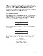
In this figure the number 230 is for example only and will vary with each supply. The
“OK” means the value being read internally is within an acceptable range and the
calibration may proceed. At this time read the output current using the volt meter and
shunt, and using the numeric keypad enter the correct current to five places. Press
ENTER when the correct current has been input. The next current calibration step is to
take a reading at a high output current level. After the previous ENTER is pressed the
warning screen shown in Figure 5-5 will be displayed.
On high output current supplies
the current shunt may get quite hot in this step and proper precautions should be taken
.
Figure 5-5
Hot Shunt Warning Screen
Proceed with the calibration by pressing ENTER again. At this time the output current
will rise to about 90% of the rating of the supply and the screen displayed in Figure 5-6
will be displayed.
Figure 5-6
Current Calibration 2
In this figure the number 3300 is for example only and will vary with each supply. The
“OK” means the value being read internally is within an acceptable range and the
calibration may proceed. At this time read the output current using the volt meter and
shunt, and using the numeric keypad enter the correct current to five places. Press
ENTER when the correct current has been input. A reading of “LOW” instead of “OK”
indicates either too high a resistance in the shunt and cables or a faulty power supply.
Voltage Calibration.
The third and fourth steps of the calibration are for the output voltage. Do not use
external sense for this step. The first of these is a reading at a low voltage (~10% of
rating); the second is at a high voltage (~90% of rating). To begin these two steps the
output of the power supply must be connected to a small load able to load the supply to
any value between 10% and 50% of the maximum current rating at full output voltage.
Connect one end of the load to the positive output of the supply and the other to the
negative output of the supply. Be sure to use adequately sized cable for the
connections. Connect the volt meter directly across the remote sense terminals (not the
load). After pressing ENTER at the screen displayed in Figure 5-6 above, the first of the
screens shown in Figure 5-7 will be displayed. A second ENTER will display the second
screen shown in Figure 5-7. This is the correct time to connect the load.
M550004-01
5-3
Summary of Contents for Sorensen DHP Series
Page 1: ...M550004 01 Rev K www programmablepower com DHP Series DC Power Supplies Operation Manual...
Page 2: ......
Page 3: ......
Page 4: ......
Page 6: ...This page intentionally left blank ii...
Page 8: ...This page intentionally left blank iv...
Page 10: ...This page intentionally left blank WA 2...
Page 44: ...This page intentionally left blank M550004 01 3 16...
Page 54: ...This page intentionally left blank M550004 01 5 6...


